Tag Archives: dc motor 220v

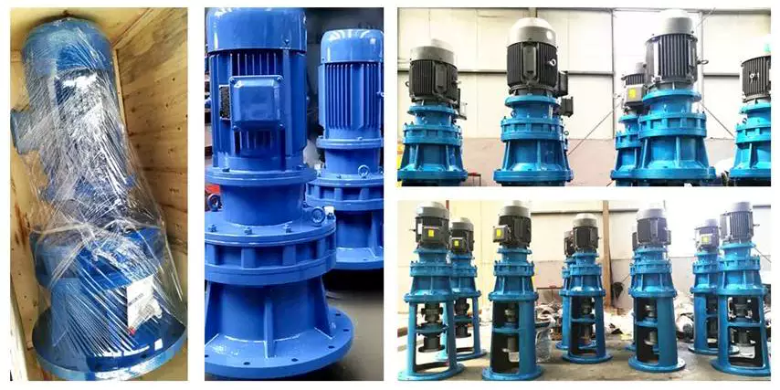
China X/B Series Miniature Cycloid Pin Wheel Reducer Cycloid DC 220V Geared Motor Speed Reducer 8000 Series Cycloidal Gear Box for Lifting Transportation with Hot selling

Item Description

X/B Sequence Miniature Cycloid Pin Wheel Reducer Cycloid DC 220V  geared motor Pace Reducer 8000 Series Cycloidal Equipment Box for Lifting Transportation

Quick Details:

Sort: XB collection Cycloidal Pin Wheel Speed Reducer    

Enter Pace: a thousand-1500rmp   

Output Velocity: .3-280rpm

Certification: ISO9001 CE          

Ex Power:.09-132KW                  

Guarantee: 1Years

US $10-99
/ Piece
|
100 Pieces

(Min. Order)

###

Application: Motor, Electric Cars, Motorcycle, Machinery, Marine, Toy, Agricultural Machinery, Car
Hardness: Soft Tooth Surface
Installation: 90 Degree
Layout: Coaxial
Gear Shape: Conical – Cylindrical Gear
Step: Stepless

###

Samples:
US$ 9999/Piece
1 Piece(Min.Order)

|
Request Sample

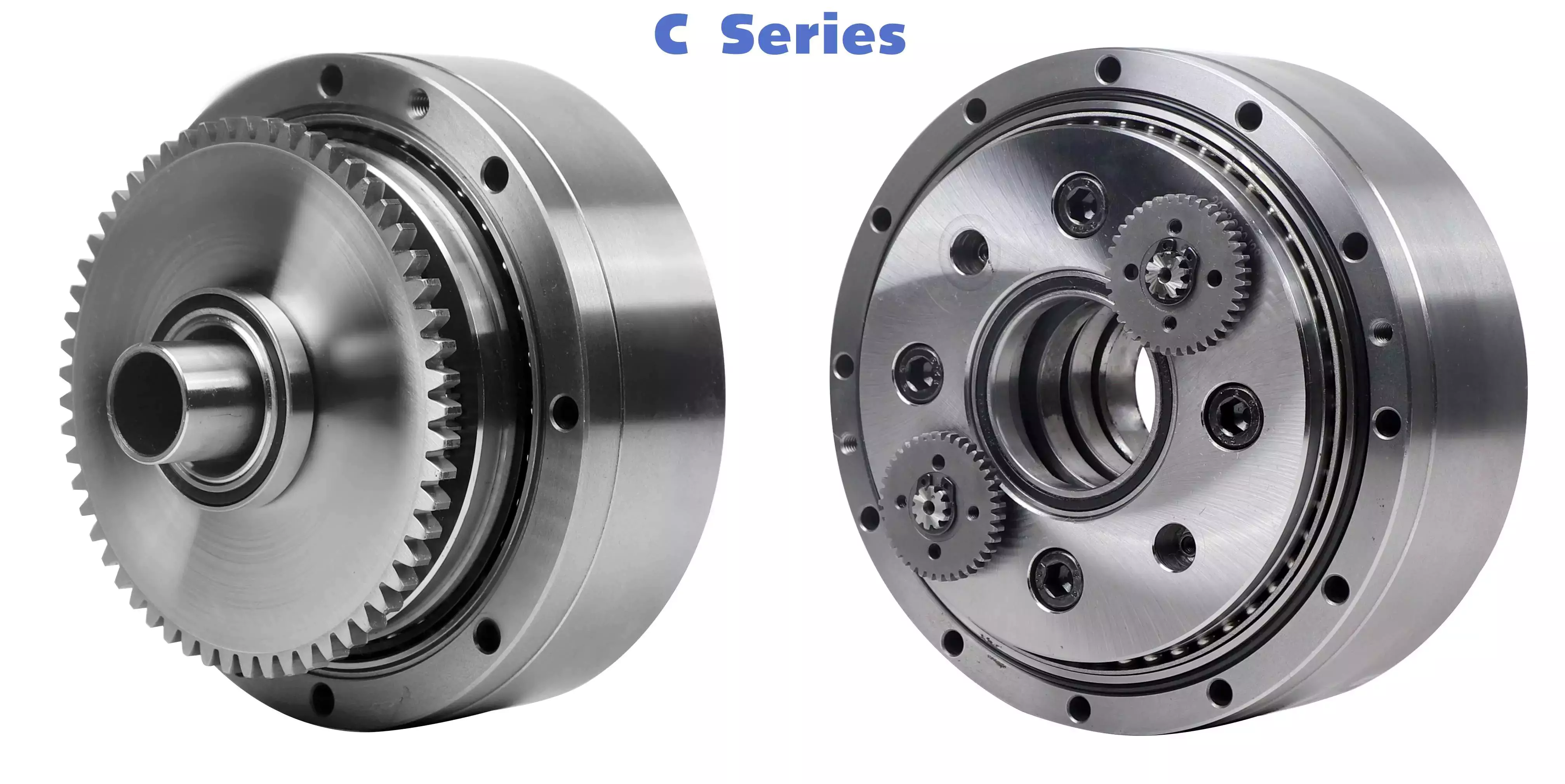
The Basics of a Cyclone Gearbox

Besides being compact, cycloidal speed reducers also offer low backlash and high ratios. Because of the small size of the drive, they are ideal for applications where space is a problem.helical gearbox
Involute gear tooth profile

Almost all gears use an involute gear tooth profile. This profile has a single curve, which means that the gear teeth do not have to be aligned closely with each other. This profile is smooth and can be manufactured easily.
Cycloid gears have a combination of epicycloid and hypocycloid curves. This makes them stronger than involute gear teeth. However, they can be more expensive to manufacture. They also have larger reduction ratios. They transmit more power than involute gears. Cycloid gears can be found in clocks.
When designing a gear, you need to consider several factors. Some of these include the number of teeth, the tooth angle and the lubrication type. Having a gear tooth that is not perfectly aligned can result in transmission error, noise and vibration.
The tooth profile of an involute gear is usually considered the best. Because of this, it is used in a wide variety of gears. Some of the most common applications for this profile are power transmission gears. However, this profile is not the best for every application.
Cycloid gears require more complex manufacturing processes than involute gear teeth. This can cause a larger tooth cost. Cycloid gears are used for less noisy applications.
Cycloid gears also transmit more power than involute gears. This can cause problems if the radii change tangentially. However, the shape is more simple than involute gears. Involute gears can handle centre sifts better.
Cycloid gears are less susceptible to transmission error. Cycloid gears have a convex surface, which makes them stronger than involute teeth. Cycloid gears also have a larger reduction ratio than involute gears. Cycloid teeth do not interfere with the mating teeth. However, they have a smaller number of teeth than involute teeth.

Rotation on the inside of the reference pitch circle of the pins

Whether a cycloidal gearbox is designed for stationary or rotating applications, the fundamental law of gearing must be observed: The ratio of angular velocities must be constant. This requires the rotation on the inside of the reference pitch circle of the pins to be constant. This is achieved through a series of cycloidal teeth, which act like tiny levers to transmit motion.
A cycloidal disc has N lobes which are rotated by three lobes per rotation around N pins. The number of lobes on a cycloidal disc is a significant factor in determining the transmission ratio.
A cycloidal disc is driven by an eccentric input shaft which is mounted to an eccentric bearing within an output shaft. As the input shaft rotates, the cycloidal disc moves around the pins of the pin disc.
The drive pin rotates at a 40 deg angle while the cycloidal disc rotates on the inside of the reference pitch circle of pins. As the drive pin rotates, it will slow the output motion. This means that the output shaft will complete only three revolutions with the input shaft, as opposed to nine revolutions with the input shaft.
The number of teeth on a cycloidal disc must be small compared to the number of surrounding pins. The disc must also be constructed with an eccentric radius. This will determine the size of the hole which will be required for the pin to fit between the pins.
When the input shaft is turned, the cycloidal disc will rotate on the inside of the reference pitch circle of roller pins. This will then transmit motion to the output shaft. The output shaft is supported by two bearings in an output housing. This design has low wear and torsional stiffness.helical gearbox
Transmission ratio

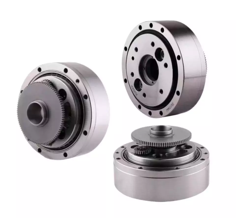
Choosing the right transmission ratio of cycloidal gearbox isn’t always easy. You might need to know the size of your gearbox before you can make an educated choice. You may also need to refer to the product catalog for guidance. For example, CZPT gearboxes have some unique ratios.
A cycloidal gear reducer is a compact and high-speed torque transmission device that reverses the direction of angular movement of the follower shaft. It consists of an eccentric cam positioned inside a cycloidal disc. Pin rollers on the follower shaft fit into matching holes in the cycloidal disc. In the process, the pins slide around the holes, in response to wobbling motion. The cycloidal disc is also capable of engaging the internal teeth of a ring-gear housing.
A cycloidal gear reducer can be used in a wide variety of applications, including industrial automation, robotics and power transmissions on boats and cranes. A cycloidal gear reducer is ideally suited for heavy duty applications with large payloads. They require specialized manufacturing processes, and are often used in equipment with precise output and high efficiency.
The cycloidal gear reducer is a relatively simple structure, but it does require some special tools. Cycloid gear reducers are also used to transmit torque, which is one of the reasons they are so popular in automation. Using a cycloidal gear reducer is a good choice for applications that require higher efficiency and lower backlash. It is also a good choice for applications where size is a concern. Cycloid gears are also a good choice for applications where high speed and high torque are required.
The transmission ratio of cycloidal gearbox is probably the most important function of a gearbox. You need to know the size of your gearbox and the type of gears it contains in order to make the right choice.

Vibration reduction

Considering the unique dynamics of a cycloidal gearbox, vibration reduction measures are required for a smooth operation. These measures can also help with the detection of faults.
A cycloidal gearbox is a gearbox with an eccentric bearing that rotates the center of the gears. It shares torque load with five outer rollers at any given time. It can be applied in many applications. It is a relatively inexpensive asset. However, if it fails, it can have significant economic impacts.
A typical input/output gearbox consists of a ring plate and two cranks mounted on the input shaft. The ring plate rotates when the input shaft rotates. There are two bearings on the output shaft.
The ring plate is a major noise source because it is not balanced. The cycloidal gear also produces noise when it meshes with the ring plate. This noise is generated by structural resonance. Several studies have been performed to solve this problem.
However, there is not much documented work on the condition monitoring of cycloidal gearboxes. In this article, we will introduce modern techniques for vibration diagnostics.
A cycloidal gearbox with a reduced reduction ratio has higher induced stresses in the cycloidal disc. In this case, the size of the output hole is larger and more material is removed from the cycloidal disc. This increase in the disc’s stresses leads to higher vibration amplitudes.
The load distribution along the width of the gear is an important design criterion. Using different gear profiles can help to optimize the transmission of torque. The contact stress of the cycloidal disc can also be investigated.
To determine the amplitude of the noise, the frequency of the gear mesh is multiplied by the shaft rate. If the RPM is relatively stable, the frequency can be used as a measure of magnitude. However, this is only accurate at close to failure.helical gearbox
Comparison with planetary gearboxes

Several differences exist between cycloidal gearboxes and planetary gearboxes. They are related to gear geometry and manufacturing processes. Among them, there are:
– The output shaft of a cycloidal gearbox has a larger torque than the input shaft. The rotational speed of the output shaft is lower than the input shaft.
– The cycloid gear disc rotates at variable velocity, while the planetary gear has a fixed speed. Consequently, the cycloid disc and output flange transmission accuracy is lower than that of the planetary gears.
– The cycloidal gearbox has a larger gripping area than the planetary gear. This is an advantage of the cycloidal gearbox in that it can handle larger loads.
– The cycloid profile has a significant impact on the quality of contact meshing between the tooth surfaces. The width of the contact ellipses increases by 90%. This is a result of the elimination of undercuts of the lobes. In this way, the contact force on the cycloid disc is decreased significantly.
– The cycloid drive has lower backlash and high torsional stiffness. This allows a cycloidal drive to be more stable against shock loads. The cycloid drive is also a compact design, which is ideally suited for applications with large transmission ratios.
– The output hub of the cycloid gearbox has movable pins and rollers. These components are attached to the ring gear in the outer gearbox. The output shaft is also turned by the planet carrier. The output hub of the cycloid system is composed of two parts: the ring gear and the output flange.
– The input shaft of a cycloidal gearbox is connected to a servomotor. The input shaft is a cylindrical element that is fixed to the planet carrier.
China X/B Series Miniature Cycloid Pin Wheel Reducer Cycloid DC 220V Geared Motor Speed Reducer 8000 Series Cycloidal Gear Box for Lifting Transportation     with Hot sellingChina X/B Series Miniature Cycloid Pin Wheel Reducer Cycloid DC 220V Geared Motor Speed Reducer 8000 Series Cycloidal Gear Box for Lifting Transportation     with Hot selling
editor by czh 2023-01-20

China manufacturer Z Medium 220V 330V 440V 550V 660V 750V 500rpm 1000rpm 60kw 160kw 240kw 300kw 480kw 550kw 160HP 200HP 250HP 280HP 300HP brush DC Motor for Pump Mining Machine with Best Sales

Product Description

Z Series DC Motor    


Product Description

Z series Medium Size DC Motor used polygon structure so that the using rate of the stator’s inner space is very high. The magnet yoke is laminated style, suitable for silicon controlled commutate power supply and it can endure the pulsating current and rapid change of current, magnetic poles are fixed by precise orientation. All the motors of the system are with compensating winding, sop the reverse performance is very well.

The insulation class of the motor is F, using of reliable insulation structure and non-menstruum vacuum pressure impregnated, guaranteeing the stability of insulation and good heat dissipation.

Electrical performance

1. Data listed in the technical data should be employed under the following conditions:

  a) Altitude above sea level maximum 1000m.

  b) Cooling air temperature 40ºC, Cooling temperature  32ºC.

  c) the motor can be installed under foul situations, but the right cooling method of cooling and defense class must be chosen. If the situation is special, need humid tropic, pls negotiable.

  d) The motor is suitable for a three-phase bridge system smoothing reactor, and also can adopt the power supply of a dc generator.

  e) The motor accord with GB755, “the ration and performance of the rotating electrical machinery”, IEC60034-1 and JB/T9577-1999 Technical requirements of Z series middle size electro motor.

2. The standard rated voltage of the electro motor is 440v, 550v, 660v, etc. The voltage of other classes can also be derived according to specific situations but must be negotiated when ordering.

3. The basic excitation style is separately excited, the exciting voltage is 220v, Voltage of other classes can also be derived according to specific situations, but must be negotiated when ordering.

4. Short time overload capacity of the motor

  The motor can be divided into 2 kinds according to the use.

  The first kind (A): is an ordinary industrial DC motor, Second Kind (B): is a metal rolling mill DC Motor.

Construction

1. The methods and protection degree of the motor

a) The method of cooling of the motor is separately-cooled, according to GB/T1993 “Method of cooling of rotating electrical machinery”, there are IC06, IC17, IC37, and IC86W. The standard entrance of cooling air is at the end of the main transmission(not the commutator side). The protection class of the motor can be divided into IP23 and IP44 according to the GB/T4942.1 and IEC34-5. If the user needs another method of cooling and defending the class, it can be negotiated.

b) the relation between the method of cooling and the protection degree of the motor pls see

Table 1.

c) the cooling method, wind pressure, cooling water flux, and motor power see: Table 2.

2. The installation and the type of motor according to the GB/T997 “the structure and installation type of rotating electrical machinery”, have IM1001(Horizontal bottom install, column biaxial) and IM1002 (Horizontal bottom install, column biaxial). If the user needs other kinds of installation structures, it must be negotiated.

3. The position of the terminal box on the standard motor is on the right side when seen from the main drive end. It can also be installed on the left side, but it must be written in the order contract.

4. The motor uses a rolling bearing, nonstop adding oil structure.

5. The motor can be installed with the following accessories at the user’s option.

a) temperature detector component can be put into stator winding and bearing room of 2 sides, and connect the outlet wire to the terminal box.

b) The non-drive party of the machine can be equipped with a tacho-generator, centrifugal starting switch, coder, and others which build up the speed meter protecting device.

c) Heater for preventing condensation can be installed in the motor, but it must be written in the other contact

6. The air-to-water heat exchanger is usually installed on the top of the motor. If the user wants to be installed on the side of the motor, the user must put forward it when ordering and settle the assistant upholder by the user himself.

7. The cooler is equipped with a wind pressure switch, temperature controller, heater for preventing condensation, and other protection devices.


Order notice

1. The motor type, power, voltage, running speed, excitation type, cooling type, number of output drafts, the position of the outlet box, etc. Must be written when ordering.

2. Pls give a clear indication of the accessory’s type, specification, and number installed on the motor when ordering.

3. If the environment of using is special, humid torrid zone type motor is needed pls write “H” after the original type.

4. If you have some special requirement of the specification and technical requirement which is not listed in the booklet, pls contact us.

Company introduction:


Packaging & Delivery
Testing Equipment

Use Field


Power 55kw– 1600KW
Voltage: 220v/330v/440/550v/660v
Speed:  rated speed reference
Protection Degree: IP22/IP44
Cooling method:  IC06, IC17, IC37,ICW37A86
Insulation Class:  F class
Duty:  S1
Package:  Export Wooden Package
Payment:  30% in advance, balance by T/T or L/C at sight

###

Frame

Built-on blower

air-to-water heat exchanger

cooling wind

Wind pressure (whisht pressure)

motor power

weight

Cooling water flux

motor power

weight

m³/hr

Pa

KW

KG

m³/hr

KW

KG

H500

10000

1900

7.5

300

19

11

900

H560

16500

2250

15.0

400

22

18.5

1100

H710

23500

2400

18.5

600

40

2*11

1600

Benefits of a Planetary Motor

A planetary motor has many benefits. Its compact design and low noise makes it a good choice for any application. Among its many uses, planetary gear motors are found in smart cars, consumer electronics, intelligent robots, communication equipment, and medical technology. They can even be found in smart homes! Read on to discover the benefits of a planetary gear motor. You’ll be amazed at how versatile and useful it is!
Motor

Self-centering planet gears ensure a symmetrical force distribution

A planetary motor is a machine with multiple, interlocking planetary gears. The output torque is inversely proportional to the diameters of the planets, and the transmission size has no bearing on the output torque. A torsional stress analysis of the retaining structure for this type of motor found a maximum shear stress of 64 MPa, which is equivalent to a safety factor of 3.1 for 6061 aluminum. Self-centering planet gears are designed to ensure a symmetrical force distribution throughout the transmission system, with the weakest component being the pinions.
A planetary gearbox consists of ring and sun gears. The pitch diameters of ring and planet gears are nearly equal. The number of teeth on these gears determines the average gear-ratio per output revolution. This error is related to the manufacturing precision of the gears. The effect of this error is a noise or vibration characteristic of the planetary gearbox.
Another design for a planetary gearbox is a traction-based variant. This design eliminates the need for timing marks and other restrictive assembly conditions. The design of the ring gear is similar to that of a pencil sharpener mechanism. The ring gear is stationary while planet gears extend into cylindrical cutters. When placed on the sun’s axis, the pencil sharpening mechanism revolves around the ring gear to sharpen the pencil.
The JDS eliminates the need for conventional planetary carriers and is mated with the self-centering planet gears by dual-function components. The dual-function components synchronize the rolling motion and traction of the gears. They also eliminate the need for a carrier and reduce the force distribution between the rotor and stator.

Metal gears

A planetary motor is a type of electric drive that uses a series of metal gears. These gears share a load attached to the output shaft to generate torque. The planetary motor is often CNC controlled, with extra-long shafts, which allow it to fit into very compact designs. These gears are available in sizes from seven millimeters to 12 millimeters. They can also be fitted with encoders.
Planetary gearing is widely used in various industrial applications, including automobile transmissions, off-road transmissions, and wheel drive motors. They are also used in bicycles to power the shift mechanism. Another use for planetary gearing is as a powertrain between an internal combustion engine and an electric motor. They are also used in forestry applications, such as debarking equipment and sawing. They can be used in other industries as well, such as pulp washers and asphalt mixers.
Planetary gear sets are composed of three types of gears: a sun gear, planet gears, and an outer ring. The sun gear transfers torque to the planet gears, and the planet gears mesh with the outer ring gear. Planet carriers are designed to deliver high-torque output at low speeds. These gears are mounted on carriers that are moved around the ring gear. The planet gears mesh with the ring gears, and the sun gear is mounted on a moveable carrier.
Plastic planetary gear motors are less expensive to produce than their metal counterparts. However, plastic gears suffer from reduced strength, rigidity, and load capacity. Metal gears are generally easier to manufacture and have less backlash. Plastic planetary gear motor bodies are also lighter and less noisy. Some of the largest plastic planetary gear motors are made in collaboration with leading suppliers. When buying a plastic planetary gear motor, be sure to consider what materials it is made of.
Motor

Encoder

The Mega Torque Planetary Encoder DC Geared Motor is designed with a Japanese Mabuchi motor RS-775WC, a 200 RPM base motor. It is capable of achieving stall torque at low speeds, which is impossible to achieve with a simple DC motor. The planetary encoder provides five pulses per revolution, making it perfect for applications requiring precise torque or position. This motor requires an 8mm hex coupling for proper use.
This encoder has a high resolution and is suitable for ZGX38REE, ZGX45RGG and ZGX50RHH. It features a magnetic disc and poles and an optical disc to feed back signals. It can count paulses as the motor passes through a hall on the circuit board. Depending on the gearbox ratio, the encoder can provide up to two million transitions per rotation.
The planetary gear motor uses a planetary gear system to distribute torque in synchrony. This minimizes the risk of gear failure and increases the overall output capacity of the device. On the other hand, a spur gear motor is a simpler design and cheaper to produce. The spur gear motor works better for lower torque applications as each gear bears all the load. As such, the torque capacity of the spur gear motor is lower than that of a planetary gear motor.
The REV UltraPlanetary gearbox is designed for FTC and has three different output shaft options. The output shaft is made of 3/8-inch hex, allowing for flexible shaft replacement. These motors are a great value as they can be used to meet a wide range of power requirements. The REV UltraPlanetary gearbox and motor are available for very reasonable prices and a female 5mm hex output shaft can be used.

Durability

One of the most common questions when selecting a planetary motor is “How durable is it?” This is a question that’s often asked by people. The good news is that planetary motors are extremely durable and can last for a long time if properly maintained. For more information, read on! This article will cover the durability and efficiency of planetary gearmotors and how you can choose the best one for your needs.
First and foremost, planetary gear sets are made from metal materials. This increases their lifespan. The planetary gear set is typically made of metals such as nickel-steel and steel. Some planetary gear motors use plastic. Steel-cut gears are the most durable and suitable for applications that require more torque. Nickel-steel gears are less durable, but are better able to hold lubricant.
Durability of planetary motor gearbox is important for applications requiring high torque versus speed. VEX VersaPlanetary gearboxes are designed for FRC(r) use and are incredibly durable. They are expensive, but they are highly customizable. The planetary gearbox can be removed for maintenance and replacement if necessary. Parts for the gearbox can be purchased separately. VEX VersaPlanetary gearboxes also feature a pinion clamped onto the motor shaft.
Dynamic modeling of the planetary gear transmission system is important for understanding its durability. In previous studies, uncoupled and coupled meshing models were used to investigate the effect of various design parameters on the vibration characteristics of the planetary gear system. This analysis requires considering the role of the mesh stiffness, structure stiffness, and moment of inertia. Moreover, dynamic models for planetary gear transmission require modeling the influence of multiple parameters, such as mesh stiffness and shaft location.
Motor

Cost

The planetary gear motor has multiple contact points that help the rotor rotate at different speeds and torques. This design is often used in stirrers and large vats of liquid. This type of motor has a low initial cost and is more commonly found in low-torque applications. A planetary gear motor has multiple contact points and is more effective for applications requiring high torque. Gear motors are often found in stirring mechanisms and conveyor belts.
A planetary gearmotor is typically made from four mechanically linked rotors. They can be used for various applications, including automotive and laboratory automation. The plastic input stage gears reduce noise at higher speeds. Steel gears can be used for high torques and a modified lubricant is often added to reduce weight and mass moment of inertia. Its low-cost design makes it an excellent choice for robots and other applications.
There are many different types of planetary gear motors available. A planetary gear motor has three gears, the sun gear and planet gears, with each sharing equal amounts of work. They are ideal for applications requiring high torque and low-resistance operation, but they require more parts than their single-stage counterparts. The steel cut gears are the most durable, and are often used in applications that require high speeds. The nickel-steel gears are more absorptive, which makes them better for holding lubricant.
A planetary gear motor is a high-performance electrical vehicle motor. A typical planetary gear motor has a 3000 rpm speed, a peak torque of 0.32 Nm, and is available in 24V, 36V, and 48V power supply. It is also quiet and efficient, requiring little maintenance and offering greater torque to a modern electric car. If you are thinking of buying a planetary gear motor, be sure to do a bit of research before purchasing one.

China Standard 29V Outer rotor brushless motor 18v BLDC 52mm brushless dc motor For Household Appliances 220v dc motor with high quality

Warranty: 3years
Model Number: AMK-MP140
Usage: BOAT, Car, Electric Bicycle, Home Appliance, Cosmetic instrument, SMART HOME
Type: GEAR MOTOR, Micro Gear Motor
Torque: 1.31~25 kg.cm
Construction: Shunt Wound
Commutation: Brush
Protect Feature: Waterproof
Speed(RPM): 3000rpm
Continuous Current(A): 0.6-5Amp
Efficiency: IE 2
Product Name: Linear Actuator
Application: Home Applicance
Color: Silver
Size: Customers’ Requirement
Noise: Low Noise Level
Function: Driven Equipment
MOQ: 100PCS
Load: 1500n

29V Outer rotor brushless motor 18v BLDC 52mm brushless dc motor For Household Appliances For Smart home Specification itemvalueWarranty3yearsPlace of OriginChinaZHangZhougBrand NameAOMEKEModel NumberAMK-MP140UsageBOAT, Car, Electric Bicycle, Home Appliance, Cosmetic instrument, SMART HOMETypeGEAR MOTORTorque1.31~25 kg.cmConstructionShunt WoundCommutationBrushProtect FeatureWaterproofSpeed(RPM)3000rpmContinuous Current(A)0.6-5AmpEfficiencyIE 2TypeMicro Gear MotorProduct NameLinear ActuatorApplicationHome ApplicanceColorSilverSizeCustomers’ RequirementNoiseLow Noise LevelFunctionDriven EquipmentMOQ100PCSLoad1500n AOMEKE is global designer and manufacturer of linear actuators, medical care system products and intelligent furniture etc. We have been producing high quality products since 2012. With over 710,000 sq.ft. of factory space, we use high-end production equipment such as laser-cutters , robotic welders, automatic CNC bending machines, automatic punches, automated powder coating paint lines, and a cutting edge inspection laboratory. This investment in precision manufacturing and quality assurance guarantee us high efficiency, and make sure our customers are provided with high quality products. Our products are manufactured in a safe, efficient, and process-driven manufacturing environment. Aomeke enforces strict manufacturing guidelines meeting efficient and high-quality standards. We achieve best-in-class quality and are backed by CE, UL962, BIFMA, FCC, ROHS, EN527, EMC, CAS, SAA, CB, PSE, GECA certifications and compliances. Backed by an innovative and well trained R&D team, extensive production capacity, and professional sales teams, Aomeke empowers customers around the world to enjoy a more health-conscious workspace. With a strict commitment to [Green, Health, and Comfort”, AOMEKE is devoted to supplying high-quality products at competitive prices, togetherbacked by a reputation for high levels of customer service to our clients. Following our quick expansion, AOMEKE has included 2 additional branches, 1 in the Netherlands and another in Thailand, and a wholly subsidiary in US to provide a better overall customer experience.

The Benefits of Using a Gear Motor

A gear motor works on the principle of conservation of angular momentum. As the smaller gear covers more RPM and the larger gear produces more torque, the ratio between the two is greater than one. Similarly, a multiple gear motor follows the principle of energy conservation, with the direction of rotation always opposite to the one that is adjacent to it. It’s easy to understand the concept behind gear motors and the various types available. Read on to learn about the different types of gears and their applications.

Electric motor

The choice of an electric motor for gear motor is largely dependent on the application. There are various motor and gearhead combinations available, and some are more efficient than others. However, it is critical to understand the application requirements and select a motor that meets these needs. In this article, we’ll examine some of the benefits of using a gear motor. The pros and cons of each type are briefly discussed. You can buy new gear motors at competitive prices, but they aren’t the most reliable or durable option for your application.
To determine which motor is best for your application, you’ll need to consider the load and speed requirements. A gear motor’s efficiency (e) can be calculated by taking the input and output values and calculating their relation. On the graph below, the input (T) and output (P) values are represented as dashed lines. The input (I) value is represented as the torque applied to the motor shaft. The output (P) is the amount of mechanical energy converted. A DC gear motor is 70% efficient at 3.75 lb-in / 2,100 rpm.
In addition to the worm gear motor, you can also choose a compact DC worm gear motor with a variable gear ratio from 7.5 to 80. It has a range of options and can be custom-made for your specific application. The 3-phase AC gear motor, on the other hand, works at a rated power of one hp and torque of 1.143.2 kg-m. The output voltage is typically 220V.
Another important factor is the output shaft orientation. There are two main orientations for gearmotors: in-line and offset. In-line output shafts are most ideal for applications with high torque and short reduction ratios. If you want to avoid backlash, choose a right angle output shaft. An offset shaft can cause the output shaft to become excessively hot. If the output shaft is angled at a certain angle, it may be too large or too small.
Motor

Gear reducer

A gear reducer is a special kind of speed reducing motor, usually used in large machinery, such as compressors. These reducers have no cooling fan and are not designed to handle heavy loads. Different purposes require different service factors. For instance, a machine that requires frequent fast accelerations and occasional load spikes needs a gear reducer with a high service factor. A gear reducer that’s designed for long production shifts should be larger than a machine that uses it for short periods of time.
A gear reducer can reduce the speed of a motor by a factor of two. The reduction ratio changes the rotation speed of the receiving member. This change in speed is often required to solve problems of inertia mismatch. The torque density of a gear reducer is measured in newton meters and will depend on the motor used. The first criterion is the configuration of the input and output shafts. A gear ratio of 2:1, for example, means that the output speed has been cut in half.
Bevel gear reducers are a good option if the input and output shafts are perpendicular. This type is very robust and is perfect for situations where the angle between two axes is small. However, bevel gear reducers are expensive and require constant maintenance. They are usually used in heavy-duty conveyors and farm equipment. The correct choice of gear reducer for gear motor is crucial for the efficiency and reliability of the mechanism. To get the best gear reducer for your application, talk to a qualified manufacturer today.
Choosing a gear reducer for a gear motor can be tricky. The wrong one can ruin an entire machine, so it’s important to know the specifics. You must know the torque and speed requirements and choose a motor with the appropriate ratio. A gear reducer should also be compatible with the motor it’s intended for. In some cases, a smaller motor with a gear reducer will work better than a larger one.
Motor

Motor shaft

Proper alignment of the motor shaft can greatly improve the performance and life span of rotating devices. The proper alignment of motors and driven instruments enhances the transfer of energy from the motor to the instrument. Incorrect alignment leads to additional noise and vibration. It may also lead to premature failure of couplings and bearings. Misalignment also results in increased shaft and coupling temperatures. Hence, proper alignment is critical to improve the efficiency of the driven instrument.
When choosing the correct type of gear train for your motor, you need to consider its energy efficiency and the torque it can handle. A helical geared motor is more efficient for high output torque applications. Depending on the required speed and torque, you can choose between an in-line and a parallel helical geared motor. Both types of gears have their advantages and disadvantages. Spur gears are widespread. They are toothed and run parallel to the motor shaft.
A planetary gear motor can also have a linear output shaft. A stepping motor should not operate at too high current to prevent demagnetization, which will lead to step loss or torque drop. Ensure that the motor and gearbox output shafts are protected from external impacts. If the motor and gearbox are not protected against bumps, they may cause thread defects. Make sure that the motor shafts and rotors are protected from external impacts.
When choosing a metal for your gear motor’s motor shaft, you should consider the cost of hot-rolled bar stock. Its outer layers are more difficult to machine. This type of material contains residual stresses and other problems that make it difficult to machine. For these applications, you should choose a high-strength steel with hard outer layers. This type of steel is cheaper, but it also has size considerations. It’s best to test each material first to determine which one suits your needs.
In addition to reducing the speed of your device, a geared motor also minimizes the torque generated by your machine. It can be used with both AC and DC power. A high-quality gear motor is vital for stirring mechanisms and conveyor belts. However, you should choose a geared motor that uses high-grade gears and provides maximum efficiency. There are many types of planetary gear motors and gears on the market, and it’s important to choose the right one.
Motor

First stage gears

The first stage gears of a gear motor are the most important components of the entire device. The motor’s power transmission is 90% efficient, but there are many factors that can affect its performance. The gear ratios used should be high enough to handle the load, but not too high that they are limiting the motor’s speed. A gear motor should also have a healthy safety factor, and the lubricant must be sufficient to overcome any of these factors.
The transmission torque of the gear changes with its speed. The transmission torque at the input side of the gear decreases, transferring a small torque to the output side. The number of teeth and the pitch circle diameters can be used to calculate the torque. The first stage gears of gear motors can be categorized as spur gears, helical gears, or worm gears. These three types of gears have different torque capacities.
The first stage helical gear is the most important part of a gear motor. Its function is to transfer rotation from one gear to the other. Its output is the gearhead. The second stage gears are connected by a carrier. They work in tandem with the first stage gear to provide the output of the gearhead. Moreover, the first stage carrier rotates in the same direction as the input pinion.
Another important component is the output torque of the gearmotor. When choosing a gearmotor, consider the starting torque, running torque, output speed, overhung and shock loads, duty cycles, and more. It is crucial to choose a gearmotor with the right ratio for the application. By choosing the proper gearmotor, you will get maximum performance with minimal operating costs and increase plant productivity. For more information on first stage gears, check out our blog.
The first stage of a gear motor is composed of a set of fixed and rotating sprockets. The first stage of these gears acts as a drive gear. Its rotational mass is a limiting factor for torque. The second stage consists of a rotating shaft. This shaft rotates in the direction of the torque axis. It is also the limiting force for the motor’s torque.

China Standard 29V Outer rotor brushless motor 18v BLDC 52mm brushless dc motor For Household Appliances 220v dc motor  with high qualityChina Standard 29V Outer rotor brushless motor 18v BLDC 52mm brushless dc motor For Household Appliances 220v dc motor  with high quality