Tag Archives: gearbox mechanism

China Bx Cycloidal Drive Transmission Gear Reducer Speed Gearbox cycloidal drive mechanism

Item Description

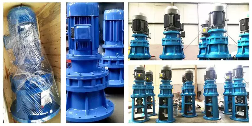
XWD2/ XWD3/XWD4/XWD5/XWD6/XWD7 /XWD8 gearbox with ac motor 

Cycloidal reducer adopts meshing cycloid pin equipment, planetary transmission principle, so usually also referred to as planetary cycloid reducer.  Planetary cycloidal reducer can be widely employed in petroleum, environmental protection, chemical, cement, transportation, textile, pharmaceutical, food, printing, lifting, mining, metallurgy, construction, power technology and other industries.
      As a travel or reduction equipment,  the machine is divided into horizontal, vertical, biaxial and straight league assembly way,and so on.  Its distinctive secure construction can exchange normal cylindrical equipment reducer and worm equipment reducer in a lot of situations. As a result, planetary cycloid equipment reducer is widely used in a variety of industries and fields, and is normally welcomed by the bulk of customers.

XWD/BWY cycloid  reducer motor details:

B sequence:

BW basedoard horizontal put in double axes type 

BL flange vertical mounted double axes kind

BWY  basedoard horizontal put in motor direct-relationship variety

BLY   flange vertical put in motor immediate-link kind

X series:

XW basedoard horizontal set up double axes variety

XL flange vertical put in double axes variety

XWD basedoard horizontal installed motor direct-connection type

XLD flange vertical mounted motor direct-relationship type


FAQ
one, Q:what is your MOQ for ac gearbox motor  ?
A: 1pc is okay for every type electrical equipment box  motor 

2, Q: What about your guarantee for your induction pace reducer motor ?
A: 1 year ,but other than gentleman-manufactured wrecked

three, Q: which payment way you can take ?
A: TT, western union .

4, Q: how about your payment way ?
A: a hundred%payment in advanced considerably less $5000 ,30% payment in superior payment , 70% payment prior to sending more than $5000.

five, Q: how about your packing of speed reduction motor  ?
A: plywood case ,if dimensions is tiny  ,we will pack with pallet for much less 1 container 

6, Q: What data must be given, if I get electric powered helical geared motor  from you ?
A: rated electrical power,  ratio or output velocity,variety ,voltage , mounting way , amount , if much more is greater , 
 

US $30-200
/ Piece
|
5 Pieces

(Min. Order)

###

Application: Motor, Machinery, Agricultural Machinery
Function: Speed Changing, Speed Reduction
Layout: Cycloidal
Hardness: Hardened Tooth Surface
Installation: Horizontal Type
Step: Single-Step

###

Customization:
US $30-200
/ Piece
|
5 Pieces

(Min. Order)

###

Application: Motor, Machinery, Agricultural Machinery
Function: Speed Changing, Speed Reduction
Layout: Cycloidal
Hardness: Hardened Tooth Surface
Installation: Horizontal Type
Step: Single-Step

###

Customization:

The Cyclonoidal Gearbox

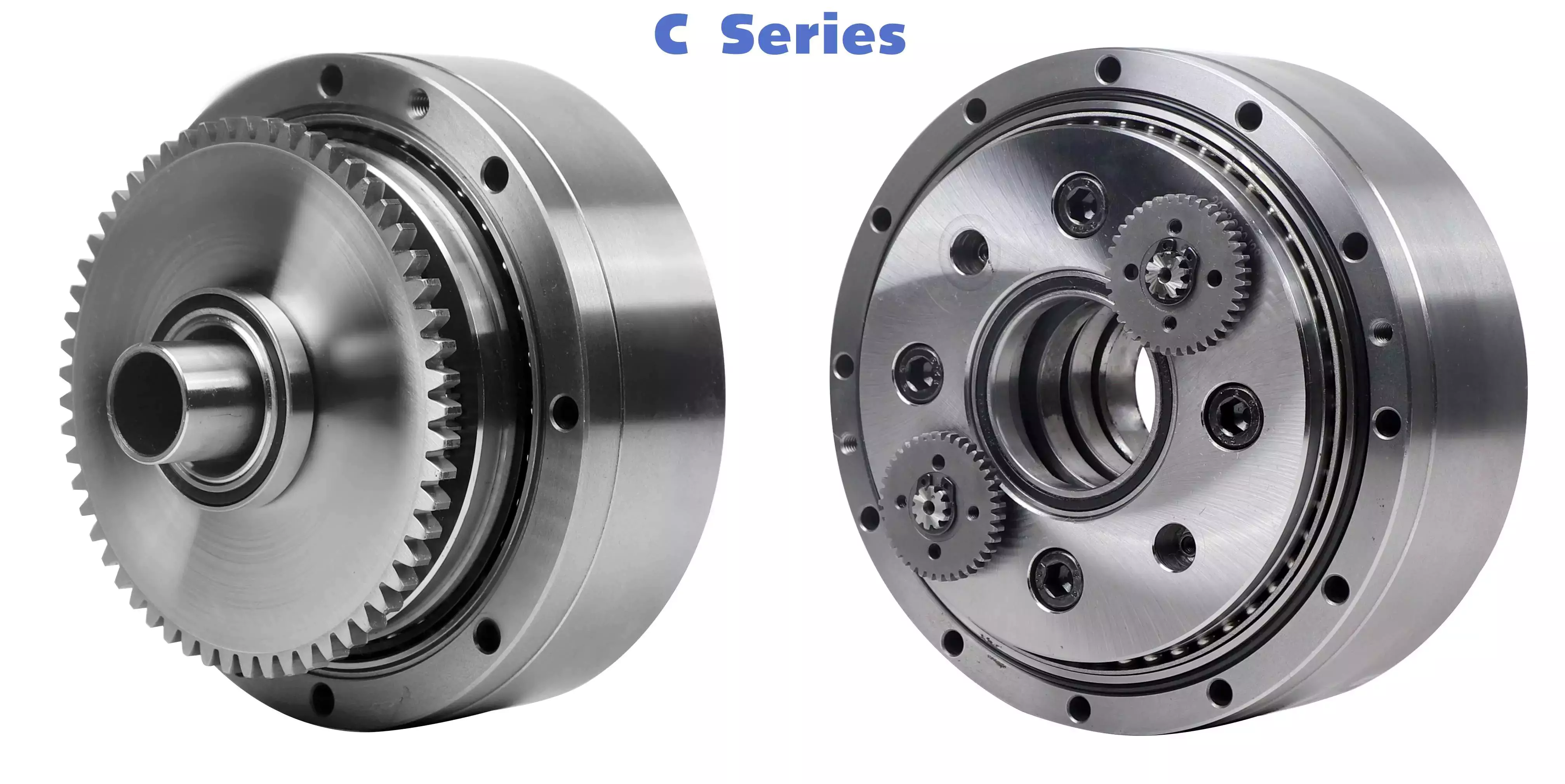
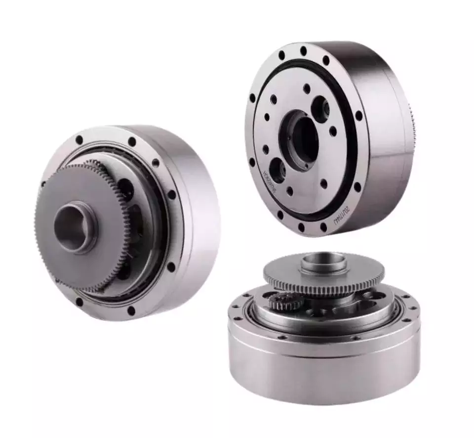
Basically, the cycloidal gearbox is a gearbox that uses a cycloidal motion to perform its rotational movement. It is a very simple and efficient design that can be used in a variety of applications. A cycloidal gearbox is often used in applications that require the movement of heavy loads. It has several advantages over the planetary gearbox, including its ability to be able to handle higher loads and higher speeds.helical gearbox
Dynamic and inertial effects of a cycloidal gearbox

Several studies have been conducted on the dynamic and inertial effects of a cycloidal gearbox. Some of them focus on operating principles, while others focus on the mathematical model of the gearbox. This paper examines the mathematical model of a cycloidal gearbox, and compares its performance with the real-world measurements. It is important to have a proper mathematical model to design and control a cycloidal gearbox. A cycloidal gearbox is a two-stage gearbox with a cycloid disc and a ring gear that revolves around its own axis.
The mathematical model is made up of more than 1.6 million elements. Each gear pair is represented by a reduced model with 500 eigenmodes. The eigenfrequency for the spur gear is 70 kHz. The modally reduced model is a good fit for the cycloidal gearbox.
The mathematical model is validated using ABAQUS software. A cycloid disc was discretized to produce a very fine model. It requires 400 element points per tooth. It was also verified using static FEA. This model was then used to model the stiction of the gears in all quadrants. This is a new approach to modelling stiction in a cycloidal gearbox. It has been shown to produce results comparable to those of the EMBS model. The results are also matched by the elastic multibody simulation model. This is a good fit for the contact forces and magnitude of the cycloid gear disc. It was also found that the transmission accuracy between the cycloid gear disc and the ring gear is about 98.5%. However, this value is lower than the transmission accuracy of the ring gear pair. The transmission error of the corrected model is about 0.3%. The transmission accuracy is less because of the lower amount of elastic deformation on the tooth flanks.
It is important to note that the most accurate contact forces for each tooth of a cycloid gearbox are not smooth. The contact force on a single tooth starts with a linear rise and then ends with a sharp drop. It is not as smooth as the contact force on a point contact, which is why it has been compared to the contact force on an ellipse contact. However, the contact on an ellipse contact is still relatively small, and the EMBS model is not able to capture this.
The FE model for the cycloid disc is about 1.6 million elements. The most important part of the FE model is the discretization of the cycloid disc. It is very important to do the discretization of the cycloid gear disc very carefully because of the high degree of vibration that it experiences. The cycloid disc has to be discretized finely so that the results are comparable to those of a static FEA. It has to be the most accurate model possible in order to be able to accurately simulate the contact forces between the cycloid disc and the ring gear.helical gearbox
Kinematics of a cycloidal drive

Using an arbitrary coordinate system, we can observe the motion of components in a cycloidal gearbox. We observe that the cycloidal disc rotates around fixed pins in a circle, while the follower shaft rotates around the eccentric cam. In addition, we see that the input shaft is mounted eccentrically to the rolling-element bearing.
We also observe that the cycloidal disc rotates independently around the eccentric bearing, while the follower shaft rotates around an axis of symmetry. We can conclude that the cycloidal disc plays a pivotal role in the kinematics of a cycloidal gearbox.
To calculate the efficiency of the cycloidal reducer, we use a model that is based on the non-linear stiffness of the contacts. In this model, the non-linearity of the contact is governed by the non-linearity of the force and the deformation in the contact. We have shown that the efficiency of the cycloidal reducer increases as the load increases. In addition, the efficiency is dependent on the sliding velocity and the deformations of the normal load. These factors are considered as the key variables to determine the efficiency of the cycloidal drive.
We also consider the efficiency of the cycloidal reducer with the input torque and the input speed. We can calculate the efficiency by dividing the net torque in the ring gear by the output torque. The efficiency can be adjusted to suit different operating conditions. The efficiency of the cycloidal drive is increased as the load increases.
The cycloidal gearbox is a multi-stage gearbox with a small shaft oin and a big shaft. It has 19 teeth and brass washers. The outer discs move in opposition to the middle disc, and are offset by 180 deg. The middle disc is twice as massive as the outer disc. The cycloidal disc has nine lobes that move by one lobe per drive shaft revolution. The number of pins in the disc should be smaller than the number of pins in the surrounding pins.
The input shaft drives an eccentric bearing that is able to transmit the power to the output shaft. In addition, the input shaft applies forces to the cycloidal disk through the intermediate bearing. The cycloidal disk then advances in 360 deg/pivot/roller steps. The output shaft pins then move around in the holes to make the output shaft rotate continuously. The input shaft applies a sinusoidal motion to maintain the constant speed of the base shaft. This sine wave causes small adjustments to the follower shaft. The forces applied to the internal sleeves are a part of the equilibrium mechanism.
In addition, we can observe that the cycloidal drive is capable of transmitting a greater torque than the planetary gear. This is due to the cycloidal gear’s larger axial length and the ring gear’s smaller hole diameter. It is also possible to achieve a positive fit between the fixed ring and the disc, which is achieved by toothing between the fixed ring and the disc. The cycloidal disk is usually designed with a short cycloid to minimize unbalance forces at high speeds.helical gearbox
Comparison with planetary gearboxes

Compared to planetary gearboxes, the cycloidal gearbox has some advantages. These advantages include: low backlash, better overload capacity, a compact design, and the ability to perform in a wide range of applications. The cycloidal gearbox has become popular in the multi-axis robotics market. The gearbox is also increasingly used in first joints and positioners.
A cycloidal gearbox is a gearbox that consists of four basic components: a cycloid disk, an output flange, a ring gear, and a fixed ring. The cycloid disk is driven by an eccentric shaft, which advances in a 360deg/pivot/roller step. The output flange is a fixed pin disc that transmits the power to the output shaft. The ring gear is a fixed ring, and the input shaft is connected to a servomotor.
The cycloidal gearbox is designed to control inertia in highly dynamic situations. These gearboxes are generally used in robotics and positioners, where they are used to position heavy loads. They are also commonly used in a wide range of industrial applications. They have higher torque density and a low backlash, making them ideal for heavy loads.
The output flange is also designed to handle a torque of up to 500 Nm. Its rotational speed is lower than the planet gearbox, but its output torque is much higher. It is designed to be a high-performance gearbox, and it can be used in applications that need high ratios and a high level of torque density. The cycloid gearbox is also less expensive and has less backlash. However, the cycloidal gearbox has disadvantages that should be considered when designing a gearbox. The main problem is vibrations.
Compared to planetary gearboxes, cycloidal gearboxes have a smaller overall size and are less expensive. In addition, the cycloid gearbox has a large reduction ratio in one stage. In general, cycloidal gearboxes have single or two stages, with the third stage being less common. However, the cycloid gearbox is not the only type of gearbox that has this type of configuration. It is also common to find a planetary gearbox with a single stage.
There are several different types of cycloidal gearboxes, and they are often referred to as cycloidal speed reducers. These gearboxes are designed for any industry that uses servos. They are shorter than planetary gearboxes, and they are larger in diameter for the same torque. Some of them are also available with a ratio lower than 30:1.
The cycloid gearbox can be a good choice for applications where there are high rotational speeds and high torque requirements. These gearboxes are also more compact than planetary gearboxes, and are suitable for high-torque applications. In addition, they are more robust and can handle shock loads. They also have low backlash, and a higher level of accuracy and positioning accuracy. They are also used in a wide range of applications, including industrial robotics.
China Bx Cycloidal Drive Transmission Gear Reducer Speed Gearbox     cycloidal drive mechanismChina Bx Cycloidal Drive Transmission Gear Reducer Speed Gearbox     cycloidal drive mechanism
editor by czh 2023-01-03

China Hangzhou Advance Marine Gearbox Ma142 Is Suitable for Small Fishing, Transport, Traffic and Passenger Boats. cycloidal drive mechanism

Merchandise Description

HangZhou  advance Marine Gearbox Marine Gearbox MA142 is suited for little fishing, transportation, site visitors and passenger boats.


Marine Gearbox MA142 possesses features of velocity reduction, ahead and astern clutching and bearing propeller thrust. It is developed of vertically offset and one-phase transmission, featuring in tiny in volume and light in weight.
Enter speed1500-2500r/minReduction ratio1.ninety seven,2.52,3.03Trans. capacity0.030kw/r/min3.540.026kw/r/min3.950.571kw/r/min4.500.019kw/r/min5.060.016kw/r/min5.470.013kw/r/minControl wayPush-and-pull adaptable shaft, electrically, pneumaticallyRated thrust8.5KNCenter distance142mmL×W×H308×520×540mmNet weight140kgFlywheelSAE11.5,10Bell housingSAE2,3


US $1,100
/ Piece
|
1 Piece

(Min. Order)

###

Application: Marine, Agricultural Machinery
Function: Clutch, Change Drive Torque, Speed Reduction
Layout: Cycloidal
Hardness: Soft Tooth Surface
Installation: Torque Arm Type
Step: Double-Step

###

Customization:
US $1,100
/ Piece
|
1 Piece

(Min. Order)

###

Application: Marine, Agricultural Machinery
Function: Clutch, Change Drive Torque, Speed Reduction
Layout: Cycloidal
Hardness: Soft Tooth Surface
Installation: Torque Arm Type
Step: Double-Step

###

Customization:

A Mathematical Model of a Cycloid Gearbox

Having a gearbox with a cycloidal rotor is an ideal design for a car or any other vehicle, as the cycloidal design can reduce the amplitude of vibration, which is a key component in car performance. Using a cycloidal gearbox is also a great way to reduce the amount of friction between the gears in the gearbox, which can help to reduce noise and wear and tear. A cycloidal gearbox is also a very efficient design for a vehicle that needs to perform under high loads, as the gearbox can be very robust against shock loads.helical gearbox

Basic design principles

cycloidal gearboxes are used for precision gearing applications. Cycloidal drives are compact and robust and offer lower backlash, torsional stiffness and a longer service life. They are also suitable for applications involving heavy loads.
Cycloidal drives are compact in size and provide very high reduction ratios. They are also very robust and can handle shock loads. Cycloidal drives are ideally suited to a wide range of drive technologies. Cycloidal gears have excellent torsional stiffness and can provide a transmission ratio of 300:1. They can also be used in applications where stacking multiple gear stages is not desired.
In order to achieve a high reduction ratio, cycloidal gears must be manufactured extremely accurately. Cycloidal gears have a curved tooth profile that removes shear forces at any point of contact. This provides a positive fit for the gear disc. This profile can be provided on a separate outer bushing or as an internal gear profile insert.
Cycloidal drives are used in marine propulsion systems, where the load plate rotates around the X and Y axis. The plate is anchored by a threaded screw hole arranged 15mm away from the center.
A secondary carrier body is used in a cycloidal gearbox to support the load plate. The secondary carrier body is composed of a mounting carrier body and a secondary carrier disc.

Low friction

Several studies have been conducted to understand the static problems of gears. In this paper, we discuss a mathematical model of a low friction cycloidal gearbox. This model is designed to calculate various parameters that affect the performance of the gearbox during production.
The model is based on a new approach that includes the stiction effect and the nonlinear friction characteristic. These parameters are not covered by the conventional rule of thumb.
The stiction effect is present when the speed direction is changed. During this time, the input torque is required to prevail over the stiction effect to generate movement. The model also enables us to calculate the magnitude of the stiction effect and its breakaway speed.
The most important thing is that the model can be used to improve the dynamic behavior of a controlled system. In this regard, the model has a high degree of accuracy. The model is tested in several quadrants of the gearbox to find the optimum stiction breakaway speed. The simulation results of the model show that this model is effective in predicting the efficiency of a low friction cycloidal gearbox.
In addition to the stiction model, we also studied the efficiency of a low friction cycloidal reducer. The reduction ratio of this gearbox was estimated from the formula. It is found that the ratio approaches negative infinity when the motor torque is close to zero Nm.

Compact

Unlike standard planetary gears, cycloidal gearboxes are compact, low friction and feature virtually zero backlash. They also offer high reduction ratios, high load capacity and high efficiency. These features make them a viable option for a variety of applications.
Cycloid disks are driven by an eccentric input shaft. They are then driven by a stationary ring gear. The ring gear rotates the cycloidal disk at a higher rate. The input shaft rotates nine times to complete a full rotation. The ring gear is designed to correct the dynamic imbalance.
CZPT cycloidal gearheads are designed for precision and stable operation. These reducers are robust and can handle large translocations. They also offer high overload protection. They are suitable for shock wave therapy. CZPT gearheads are also well suited for applications with critical positioning accuracy. They also require low assembly and design costs. They are designed for long service life and low hysteresis loss.
CZPT cycloidal reducers are used in a variety of industrial applications, including CNC machining centers, robot positioners and manipulators. They offer a unique design that can handle high forces on the output axis, and are especially suitable for large translocations. These gearheads are highly efficient, reducing costs, and are available in a variety of sizes. They are ideal for applications that require millimetre accuracy.

High reduction ratios

Compared to other gearboxes, cycloidal gearboxes offer high reduction ratios and small backlash. They are also less expensive. Cycloid gearboxes can be used in a variety of industries. They are suitable for robotic applications. They also have high efficiency and load capacity.
A cycloidal gearbox works by rotating a cycloidal disc. This disc contains holes that are bigger than the pins on the output shaft. When the disc is rotated, the output pins move in the holes to generate a steady output shaft rotation. This type of gearbox does not require stacking stages.
Cycloid gearboxes are usually shorter than planetary gearboxes. Moreover, they are more robust and can transmit higher torques.
Cycloid gearboxes have an eccentric cam that drives the cycloidal disc. The cycloidal disc advances in 360deg/pivot/roller steps. It also rotates in an eccentric pattern. It meshes with the ring-gear housing. It also engages the internal teeth of the ring-gear housing.
The number of lobes on the cycloidal disc is not sufficient to generate a good transmission ratio. In fact, the number of lobes must be less than the number of pins surrounding the cycloidal disc.
The cycloidal disc is rotated by an eccentric cam that extends from the base shaft. The cam also spins inside the cycloidal disc. The eccentric motion of the cam helps the cycloidal disc rotate around the pins of the ring-gear housing.helical gearbox

Reducing amplitude of the vibration

Various approaches to reducing amplitude of the vibration in a cycloidal gearbox have been studied. These approaches are based on the kinematic analysis of gearbox.
A cycloidal gearbox is a gearbox that consists of bearings, gears, and an eccentric bearing that drives a cycloidal disc. This gearbox has a high reduction ratio, which is achieved by a series of output shaft pins that drive the output shaft as the disc rotates.
The test bench used in the studies has four sensors. Each sensor acquires signals with different signal processing techniques. In addition, there is a tachometer that acquires variations in rotational velocity at the input side.
The kinematic study of the robotic gearbox was performed to understand the frequency of vibrations and to determine whether the gearbox is faulty. It was found that the gearbox is in healthy operation when the amplitude of the x and y is low. However, when the amplitude is high, it is indicative of a malfunctioning element.
The frequency analysis of vibration signals is performed for both cyclostationary and noncyclostationary conditions. The frequencies that are selected are those that appear in both types of conditions.

Robust against shock loads

Compared to traditional gearboxes, cycloidal gearboxes have significant benefits when it comes to shock loads. These include high shock-load capacity, high efficiency, reduced cost, lower weight, lower friction, and better positioning accuracy.
Cycloid gears can be used to replace traditional planetary gears in applications where inertia is important, such as the transportation of heavy loads. They have a lighter design and can be manufactured to a more compact size, which helps reduce cost and installation expense. Cycloid gears are also able to provide transmission ratios of up to 300:1 in a small package.
Cycloid gears are also suitable for applications where a long service life is essential. Their radial clamping ring reduces inertia by up to 39%. Cycloid gears have a torsional stiffness that is five times higher than that of conventional planetary gears.
Cycloid gearboxes can provide significant improvements in concrete mixers. They are a highly efficient design, which allows for important innovations. They are also ideal for servo applications, machine tools, and medical technology. They feature user-friendly screw connections, effective corrosion protection, and effective handling.
Cycloid gears are especially useful for applications with critical positioning accuracy. For example, in the control of large parabolic antennas, high shock load capacity is required to maintain accuracy. Cycloid gears can withstand shock loads up to 500% of their rated torque.helical gearbox

Inertial effects

Various studies have been conducted to investigate the static problems of gears. However, there is still a need for a proper model to investigate the dynamic behaviour of a controlled system. For this, a mathematical model of a cycloidal gearbox has been developed. The presented model is a simple model that can be used as the basis for a more complex mechanical model.
The mathematical model is based on the cycloidal gearbox’s mechanical construction and has a nonlinear friction characteristic. The model is able to reproduce the current peaks and breaks at standstill. It also considers the stiction effect. However, it does not cover backlash or torsional stiffness.
This model is used to calculate the torque generating current and the inertia of the motor. These values are then compared with the real system measurement. The results show that the simulation results are very close to the real system measurement.
Several parameters are considered in the model to improve its dynamic behaviour. These parameters are calculated from the harmonic drive system analysis. These are torque-generating current, inertia, and the contact forces of the rotating parts.
The model has a high level of accuracy and can be used for motor control. It is also able to reproduce the dynamic behaviour of a controlled system.
China Hangzhou Advance Marine Gearbox Ma142 Is Suitable for Small Fishing, Transport, Traffic and Passenger Boats.     cycloidal drive mechanismChina Hangzhou Advance Marine Gearbox Ma142 Is Suitable for Small Fishing, Transport, Traffic and Passenger Boats.     cycloidal drive mechanism
editor by czh 2022-12-27