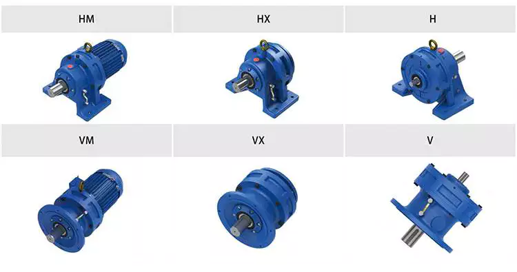
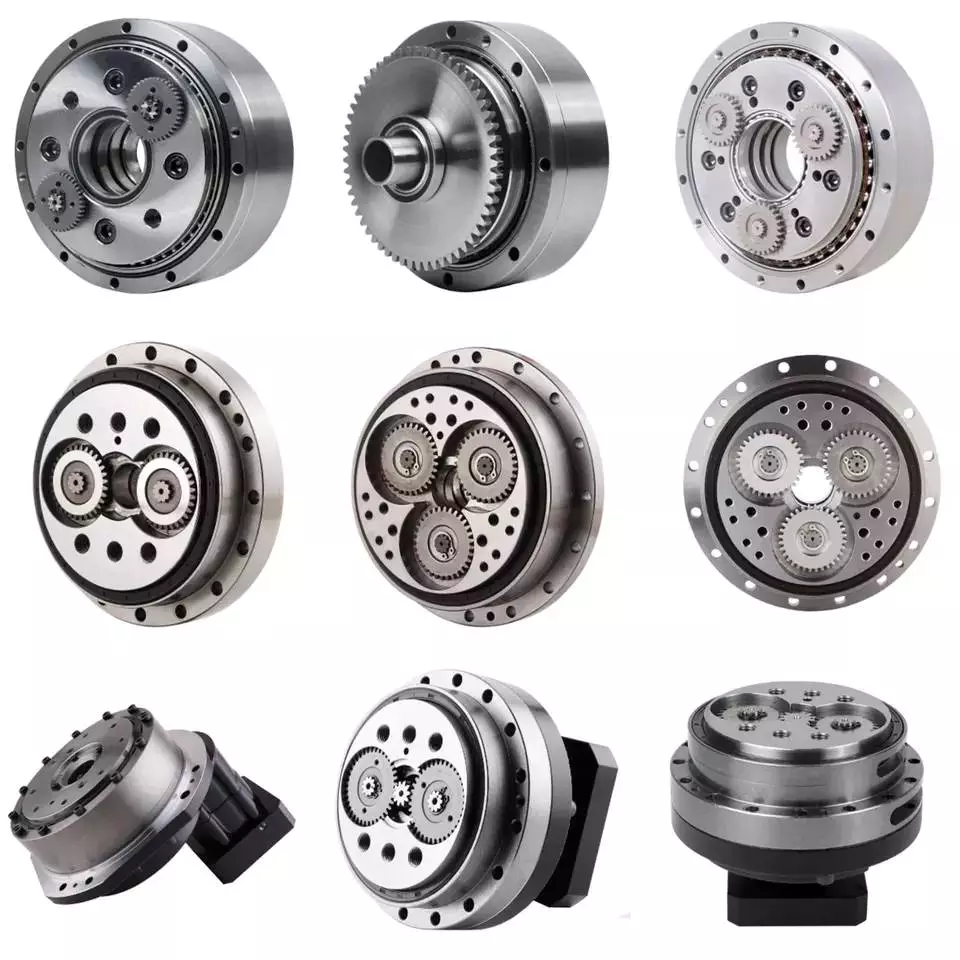
Solution Description
15r/m .2KW Far more Than 6000hr Lifestyle Time 10C BX RVC Series Hollow Variety Mounted Higher Precision Cycloidal Gearbox
Design:10CBX-RVC
Much more Code And Specification:
| E sequence | C sequence | ||||
| Code | Define dimension | General model | Code | Define dimension | The unique code |
| a hundred and twenty | Φ122 | 6E | 10C | Φ145 | a hundred and fifty |
| one hundred fifty | Φ145 | 20E | 27C | Φ181 | 180 |
| 190 | Φ190 | 40E | 50C | Φ222 | 220 |
| 220 | Φ222 | 80E | 100C | Φ250 | 250 |
| 250 | Φ244 | 110E | 200C | Φ345 | 350 |
| 280 | Φ280 | 160E | 320C | Φ440 | 440 |
| 320 | Φ325 | 320E | 500C | Φ520 | 520 |
| 370 | Φ370 | 450E | |||
Equipment ratio And Specification
| E Collection | C Collection | ||
| Code | Reduction Ratio | New code | Monomer reduction ratio |
| a hundred and twenty | forty three,53.5,59,seventy nine,103 | 10CBX | 27.00 |
| 150 | 81,a hundred and five,121,141,161 | 27CBX | 36.57 |
| a hundred ninety | 81,a hundred and five,121,153 | 50CBX | 32.54 |
| 220 | eighty one,one hundred and one,121,153 | 100CBX | 36.seventy five |
| 250 | eighty one,111,161,one hundred seventy five.28 | 200CBX | 34.86 |
| 280 | 81,101,129,one hundred forty five,171 | 320CBX | 35.sixty one |
| 320 | eighty one,one zero one,118.5,129,141,171,185 | 500CBX | 37.34 |
| 370 | eighty one,101,118.5,129,154.8,171,192.4 | ||
| Note 1: E sequence,such as by the shell(pin shell)output,the corresponding reduction ratio by 1 | |||
| Note 2: C sequence equipment ratio refers to the motor mounted in the casing of the reduction ratio,if set up on the output flange aspect,the corresponding reduction ratio by 1 | |||
Reducer type code
REV: major bearing built-in E type
RVC: hollow type
REA: with enter flange E type
RCA: with input flange hollow variety
Application:
Company Data
FAQ
Q: What’re your primary items?
A: We at present generate Brushed Dc Motors, Brushed Dc Equipment Motors, Planetary Dc Equipment Motors, Brushless Dc Motors, Stepper motors, Ac Motors and Large Precision Planetary Equipment Box etc. You can check out the technical specs for earlier mentioned motors on our internet site and you can e-mail us to recommend required motors per your specification way too.
Q: How to pick a appropriate motor?
A:If you have motor photographs or drawings to demonstrate us, or you have thorough specs like voltage, velocity, torque, motor dimensions, doing work manner of the motor, essential life time and sound stage and many others, remember to do not hesitate to allow us know, then we can suggest suited motor for every your ask for accordingly.
Q: Do you have a custom-made service for your regular motors?
A: Indeed, we can personalize for each your ask for for the voltage, velocity, torque and shaft size/form. If you want extra wires/cables soldered on the terminal or require to insert connectors, or capacitors or EMC we can make it also.
Q: Do you have an specific style provider for motors?
A: Sure, we would like to layout motors individually for our buyers, but it may possibly need to have some mildew developing cost and design and style charge.
Q: What is your guide time?
A: Usually speaking, our standard regular product will need fifteen-30days, a bit lengthier for custom-made merchandise. But we are quite versatile on the direct time, it will count on the certain orders.
You should speak to us if you have in depth requests, thank you !
| To Be Negotiated | 1 Piece (Min. Order) |
###
| Application: | Machinery, Robotic |
|---|---|
| Hardness: | Hardened Tooth Surface |
| Installation: | Vertical Type |
| Layout: | Coaxial |
| Gear Shape: | Cylindrical Gear |
| Step: | Double-Step |
###
| Customization: |
Available
|
|---|
###
| E series | C series | ||||
| Code | Outline dimension | General model | Code | Outline dimension | The original code |
| 120 | Φ122 | 6E | 10C | Φ145 | 150 |
| 150 | Φ145 | 20E | 27C | Φ181 | 180 |
| 190 | Φ190 | 40E | 50C | Φ222 | 220 |
| 220 | Φ222 | 80E | 100C | Φ250 | 250 |
| 250 | Φ244 | 110E | 200C | Φ345 | 350 |
| 280 | Φ280 | 160E | 320C | Φ440 | 440 |
| 320 | Φ325 | 320E | 500C | Φ520 | 520 |
| 370 | Φ370 | 450E | |||
###
| E Series | C Series | ||
| Code | Reduction Ratio | New code | Monomer reduction ratio |
| 120 | 43,53.5,59,79,103 | 10CBX | 27.00 |
| 150 | 81,105,121,141,161 | 27CBX | 36.57 |
| 190 | 81,105,121,153 | 50CBX | 32.54 |
| 220 | 81,101,121,153 | 100CBX | 36.75 |
| 250 | 81,111,161,175.28 | 200CBX | 34.86 |
| 280 | 81,101,129,145,171 | 320CBX | 35.61 |
| 320 | 81,101,118.5,129,141,171,185 | 500CBX | 37.34 |
| 370 | 81,101,118.5,129,154.8,171,192.4 | ||
| Note 1: E series,such as by the shell(pin shell)output,the corresponding reduction ratio by 1 | |||
| Note 2: C series gear ratio refers to the motor installed in the casing of the reduction ratio,if installed on the output flange side,the corresponding reduction ratio by 1 | |||
Condition Monitoring of Cyclone Gearboxes
Whether you’re considering using a cycloidal gearbox in your home, office, or garage, you’ll want to make sure it’s made of quality material. You also want to make sure it’s designed properly, so it won’t be damaged by vibrations.
Planetary gearboxes
Compared to cycloidal gearboxes, planetary gearboxes are lighter and more compact, but they lack the precision and durability of the former. They are better suited for applications with high torque or speed requirements. For this reason, they are usually used in robotics applications. But, cycloidal gearboxes are still better for some applications, including those involving shock loads.
There are many factors that affect the performance of gearboxes during production. One of these is the number of teeth. In the case of planetary gearboxes, the number of teeth increases with the number of planets. The number of teeth is reduced in cycloidal gearboxes, which results in higher transmission ratios. These gearboxes also have lower breakaway torques, which means that they can be controlled more easily by the user.
A cycloid gearbox is comprised of three main parts: the ring gear, the sun gear, and the input shaft. The ring gear is fixed in the gearbox, while the sun gear transmits the rotation to the planet gears. The input shaft transfers motion to the sun gear, which in turn transmits it to the output shaft. The output shaft has a larger torque than the input shaft.
Cycloid gears have better torsional stiffness, lower wear, and lower Hertzian contact stress. However, they are also larger in size and require highly accurate manufacturing. Cycloid gears can be more difficult to manufacture than involute gears, which require large amounts of precision.
Cycloid gears can offer transmission ratios up to 300:1, and they can do this in a small package. They also have lower wear and friction, which makes them ideal for applications that require a high transmission ratio.
Cycloid gearboxes are usually equipped with a backlash of about one angular minute. This backlash provides the precision and control necessary for accurate movement. They also provide low wear and shock load capacity.
Planetary gearboxes are available in single and two-stage designs, which increase in length as stages are added. In addition to the two stages, they can be equipped with an optional output bearing, which takes up mounting space. In some applications, a third stage is also available.
Involute gears
Generally, involute gears are more complex to manufacture than cycloidal gears. For example, an involute gear tooth profile has a single curve while a cycloidal gear tooth profile has two curves. In addition, the involute curve is not within the base circle.
The involute curve is a very important component of a gear tooth and it can significantly influence the quality of contact meshing between teeth. Various works have been done on the subject, mainly focusing on the operating principles. In addition, the most important characteristic of the double-enveloping cycloid drive is its double contact lines between the meshing tooth pairs.
Cycloid gears are more powerful, less noisy, and last longer than involute gears. They also require less manufacturing operations during production. However, cycloid gears are more expensive than involute gears. Involute gears are more commonly used in linear motions while cycloid gears are used for rotary motions.
Although cycloid gears are more technically advanced, involute gears have the superior quality and are more aesthetically pleasing. Cycloid gears are used in various industrial applications such as pumps and compressors. They are also widely used in the watch industry. Nevertheless, involute gears have not yet replaced cycloid gears in the watch industry.
The cycloid disc has a number of pins around its outer edge, while an involute gear has only a single curve for the teeth. In addition, cycloid gears have a more robust and reliable design. Involute gears, on the other hand, have a cheaper rack cutter and less expensive involute teeth.
The cycloid disc’s transmission accuracy is about 98.5%, while the ring gear’s transmission accuracy is about 96%. The cycloid disc’s rotational velocity has a magnitude of 3 rad/s. A small change in the center distance does not affect the transmission accuracy. However, rotational velocity fluctuation can affect the transmission accuracy.
Cycloid gears also have the cycloid gear disc’s rotational velocity. The disc has N lobes. However, the cycloid gear disc’s transmission accuracy is still not perfect. This is because of the large rotational angles between the lobes. This also makes it difficult to manufacture.
Vibrations
Using modern techniques for vibration diagnostics and data-driven methods, this article presents a new approach to condition monitoring of cycloidal gearboxes. This approach focuses on detecting the root cause of gearbox failure. The article aims to provide a unified approach to gear designers.
A cycloidal gearbox is a high-precision gearbox that is used in heavy-duty machines. It has a large reduction ratio, which makes it necessary to have a very large input speed. Cycloid gears have high accuracy, but they are susceptible to vibration issues. In this article, the authors describe how a cycloidal gearbox works and how vibrations are measured. They also show how this gearbox can be used to detect faults.
The gearbox is used in positioners, multi-axis robots, and heavy-duty machines. The main characteristics of this gearbox are the high accuracy, the overload capacity, and the large reduction ratio.
There is little documentation on vibrations and condition monitoring of cycloidal gearboxes. The authors describe their approach to the problem, using a cycloidal gearbox and a testing bench. Their approach involves measuring the frequency of the gearbox with different input speeds.
The results show a good separation between the healthy and damaged states. Fault frequencies show up in the lower orders of frequencies. Faults can be detected using binning, which eliminates the need for a tachometer. In addition, binning is combined with Principal Component Analysis to determine the state of the gearbox.
This method is compared to traditional techniques. In addition, the results show how binning can be used to calculate the defect frequencies of the bearings. It is also used to determine the frequencies of the components.
The signals from the test bench are acquired using four sensors. These sensors are medium sensitivity 100 mV/g accelerometers. The signals are then processed using different signal processing techniques. The results show that the vibration signals are correlated with the internal motion of the gearbox. This information is used to identify the internal frequency of the transmission.
The frequency analysis of vibration signals is performed in cyclostationary and noncyclostationary conditions. The signals are then analyzed to determine the magnitude of the gear meshing frequency.
Design
Using precision gearboxes, servomotors can now control heavy loads at high speed. Unlike cam indexing devices, cycloidal gears provide extremely accurate positioning and high torque. They also provide excellent torsional stiffness and shock load capacity.
Cycloid gears are specially designed to minimize vibration at high RPM. Unlike involute gears, they are not stacked, which reduces friction and forces experienced by each tooth. In addition, cycloidal gears have lower Hertzian contact stress.
Cycloid gears are often used in multi-axis robots for positioners. They can provide transmission ratios as high as 300:1 in a compact package. They are also used in first joints in heavy machines. However, they require extremely accurate manufacturing. They are also more difficult to produce than involute gears.
A cycloidal gearbox is a type of planetary gearbox. Cycloid gears are specially designed for high gear ratios. They also have the ability to provide a large reduction ratio in a single stage. They are increasingly used in first joints in heavy machines. They are also becoming more common in robotics.
In order to achieve a large reduction ratio, the input speed of the gear must be very high. Generally, the input speed is between 500 rpm and 4500 rpm. However, in some cases, the input speed may be lower.
A cycloid is formed by rolling a rolling circle on a base circle. The ratio between the rolling circle diameter and the base circle diameter determines the shape of the cycloid. A hypocycloid is formed by rolling primarily on the inside of the base circle, while an epicycloid is formed by rolling primarily on the outside of the base circle.
Cycloid gears have a very small backlash, which minimizes the forces experienced by each tooth. These gears also have a good torsional stiffness, low friction, and shock load capacity. They also provide the best positioning accuracy.
The cycloidal gearbox was designed and built at Radom University. The design was based on three different cycloidal gears. The first pair had the external profile at the nominal dimension, while the second pair had the profile minus tolerance. The load plate had threaded screw holes arranged 15 mm away from the center.

editor by czh 2023-01-25