Product Description
Overview
Product Description
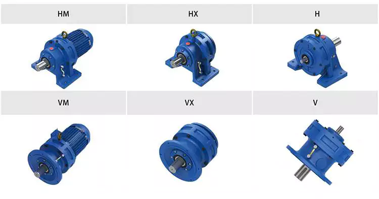
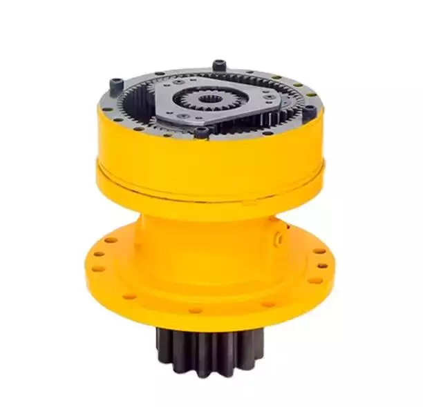
Wide Selection of Gearbox Products
The gearbox usually adopts a general design scheme, but in special cases, the design scheme of the gearbox can be changed according to the demands of the user, and it can be modified into an industry-specific gearbox. In the design scheme of the gearbox, the parallel shaft, vertical shaft, general box, and various parts can be changed
Advantages
- Absorption of very high torques and axial forces
- No need for separate thrust housing & bearing.
- Easy alignment (screw directly fits into the vore of gear box)
- Easy to assemble & dismantle.
- Very heavy duty spherical roller thrust bearing is provided.
- Power saving. (you may save up to 20 % power.)
- Less requirement of space.
- For bigger sizes water cooling is provided
- No maintenance required except periodic oil level checking.
- Higher productivity
Features
- Twin Screw Extruder Gearboxes offer the dual shaft counter rotating. The range is available for various center distances
- The gearboxes are available with co-rotating and counter rotating variants
- To work under heavy loading force, the high level dissipation and oil lubrication system are provided. The axial roller type swivel thrust with the thrust bearing coupled in tandem way support the axial thrust
- High torque and high speed output rate
Processing Characteristics of Screw Shaft:
1.Suitable suggestion on material to ensure components performance and extend lifetime of products.
2.Professional technical team can provide surveying and mapping support.
3.All components are finished by CNC machine.
4.Sophisticated quality management system ensure superior quality.
Basic Info.
| Warranty: 1 year | Weight (KG): 500 KG |
| Place of Origin: HangZhou, China |
Gearing Arrangement: helical |
| ratio: 8-20 |
Output Torque: 2*176 |
| standard: JB/T8853-2001 |
Certificate: CE |
| Heat treatment: High-frequency Hardening |
Efficiency: 94%~98%(depends on the transmission stage) |
| Customized support:OEM ODM | Input/output shaft material 40Cr |
| Package: Wooden case |
Mount position: Flange, hollow shaft, CZPT shaft |
| After-sale:Online 24/7 Installation Xihu (West Lake) Dis. | advantage: excellent quality |
| Reduction radio: 3:1 |
Mount Position: Horizontal Foot Mounted Vertical |
| Input Speed: 1500 |
Output Speed: 500 |
Packaging & delivery
|
Packing: wooden case packing |
|
| Port: HangZhou Port |
Applications
X helical gear units for double-screw extruders with parallel drive shafts and the same direction of screw rotation are used mainly in the manufacture of granulates and the refining of raw plastics. Other areas of application include:
- Paint and lacquer industry
- Washing agent industry
- Foodstuff industry (e.g. bread, pasta)
- Animal-feed industry (dog, cat other animal food
Maintenance of the gearbox of the dual-screw extruder
1. The gear box of the dual-screw extruder should be well-ventilated, and the working environment temperature should be within the range of 5-35 °C.
2. Always check the oil quantity of the gear lubricating oil in the box to ensure that the transmission parts in the box are well lubricated.
3. Pay attention to check the bearing parts of the box frequently. The oil temperature of the oil tank of the transmission box should not exceed 70 ºC during operation.
4. The newly put into use gearbox needs to replace the lubricating oil after 250 hours of operation. The oil change time depends on the state of the oil. It is recommended to replace it after 4000-8000 hours of operation or once a year.
5. The gearbox of the dual-screw extruder needs to be regularly maintained and inspected once a year
Operating Process
1. The gear on the input shaft is driven by the motor and starts to rotate.
2. The rotating input gear meshes with other gears inside the gearbox, transmitting power.
3. Different-sized gears within the gearbox are combined to form a gear train. Through continuous meshing and rotation, the high-speed, low-torque power from the input shaft gradually converts into low-speed, high-torque output.
4. The output shaft is connected to the last gear and transfers the output torque to the load.
5. Gear reduction gearboxes typically include lubrication and cooling systems to ensure smooth operation and prevent overheating and damage.
6. Our extruder gearbox converts high-speed, low-torque power into low-speed, high-torque output by changing the size ratios and meshing arrangements of different gears, achieving the function of speed reduction.
Types of Gearboxes:
Based on customer requirements, gear reduction gearboxes can be classified according to the size of the output shaft, center distance of the output shaft, output speed, and torque. Alternatively, we can provide several commonly used types of gearboxes for customers to choose from.
Product Service
|
24-hour Hotline
No matter when and where to call we can find our service to you.
|
Pre-sales Consultation
We have 5 sales people online, and whether you have any question can be solved through online communication. |
After-sales Services
Receive products have any questions about the product, can look for us,we will help you deal with the the first time,to your satisfaction. |
Exhibition
Certificate
Company profile
ZheJiang Arrow Machinery Co., Ltd.is a company specializing in R&D, production, sales, application promotion of food engineering projects. As 1 of the largest scaled food processing equipment &whole plant engineering problem solvers in China, machines served for more than 970 companies, export to 116 countries, area, more than 20 years engineering team, we recognize that quality equals value, aims to create a great future together with global customers.
FAQ
1. Q: How about Arrow Machinery?
R: ZheJiang Arrow Machinery Co., Ltd. is a High-Tech company. Our firm is composed of a strong
team which has substantial experience in R&D, manufacture, technique and sales service and has
specialized in extruder industry for 10 years,leading screw barrel manufacturer in China.
2. Q:What’s Arrow machinery’s capacity?
R:Company is in strict accordance with CE and ISO9001 quality certification system.There are over 200
models of extruders and spare parts.
3. Q:What’s the delivery time?
R:For regular size, we have finished stock and semi-finished stock, 2 weeks max enough
for customized, normally within 20days .
4. Q:How about the gearbox quality and price?
R: top quality in China with competitive price and globle after-sale service
5. Q:what’s the life time and guarantee buy from Arrow machinery ?
R: 3~5years life time for nitriding ones and bimtallic ones will be longer
One year min. Guarantee.
6.Q:Where is Arrow Machinery factory and how to reach there?
R:NO.47 Chengbohu Road, Xihu (West Lake) Dis. District,HangZhou City, China. You can take the train or plane to HangZhou and we can pick you up.
7.Q:How to contact with you?
R:just reply to me if have any question.
|
Shipping Cost:
Estimated freight per unit. |
To be negotiated |
|---|
| Application: | Motor, Machinery |
|---|---|
| Function: | Distribution Power, Change Drive Torque, Change Drive Direction, Speed Changing, Speed Reduction, Speed Increase |
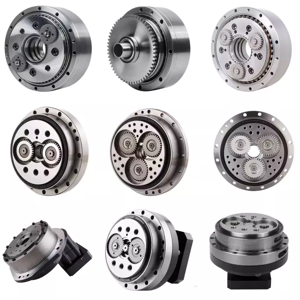
| Layout: | Cycloidal |
| Customization: |
Available
| Customized Request |
|---|

How to Use a Cyclone Gearbox
Often, a cycloidal gearbox is used in order to achieve a torque transfer from a motor or pump. This type of gearbox is often a common choice as it has a number of advantages over a regular gearbox. Its main advantage is that it is easy to make, which means that it can be incorporated into a variety of applications. However, if you want to use a cycloidal gearbox, there are a few things that you need to know. These include the operation principle, the structure and the dynamic and inertial effects that come with it.
Dynamic and inertial effects
Several studies have been carried out on the static and dynamic properties of cycloidal gears. The study of these effects is beneficial in assisting optimal design of cycloidal speed reducers.
In this paper, the dynamic and inertial effects of a two-stage cycloidal speed reducer have been investigated using the CZPT program package. Moreover, a new model for cycloidal reducers based on non-linear contact dynamics has been developed. The new model aims to predict several operational conditions.
The normal excitation contact force for the cycloid discs of the first and second stage is very similar. However, the total deformation at the contact point is different. This effect is mainly due to the system’s own oscillations. The cycloid discs of the second stage turn around the ring gear roller with a 180deg angle. This angle is a significant contributor to the torque loads. The total excitation force on the cycloid discs of first and second stage is 1848 N and 2068.7 N, respectively.
In order to analyze the contact stress, different gear profiles were investigated. The mesh density was considered as an important design criterion. It was found that a bigger hole reduces the material content of the cycloidal disc and results in more stresses.
Moreover, it is possible to reduce the contact forces in a more efficient manner by changing the geometric parameters. This can be done by mesh refinement along the disc width. The cycloidal disc has the greatest influence on the output results.
The efficiency of a cycloidal drive increases with the increase in load. The efficiency of a cycloidal reducer also depends on the eccentricity of the input shaft and the cycloidal plate. The efficiency curve for small loads is linear. However, for the larger loads, the efficiency curve becomes more non-linear. This is because the stiffness of the cycloid reducer increases as the load increases.
Structure
Despite the fact that it looks like a complicated engineering puzzle, the construction of a cycloidal gearbox is actually quite simple. The key elements are the base, the load plate and the thrust bearing. All these elements work together to create a stable, compact gearbox.
The base is a circular section with several cylindrical pins around its outer edge. The pins are fixed on a fixed ring that holds them in a circular path. The ring serves as a reference circle. The circle’s size is approximately 5mm in diameter.
The load plate is a series of threaded screw holes. These are arranged 15mm away from the center. These are used to anchor external structures. The load plate must be rotated around the X and Y axis.
The thrust bearing is placed on top of the load plate. The bearing is made of an internal diameter of 35mm and an external diameter of 52mm. It is used to allow rotation around the Z axis.
The cycloidal disc is the centerpiece of the cycloidal gearbox. The disc has holes for the pins that drive the output shaft. The holes are larger than those used in output roller pins. The disc also has a reduced eccentricity.
The pins are attached to the cycloidal disc by rolling pins. The pins are made of a material that provides mechanical support for the drive during high-torque situations. The pins have a 9mm external diameter. The disc has a number of lobes and is rotated by one lobe per shaft revolution.
The cycloidal gearbox also has a top cover that helps keep the components together. The cover has a pocket for tools. The top cover also has threads that screw into the casing.
Operation principle
Among many types of gear transmissions, cycloidal gearboxes are used in heavy machinery and multi-axis robots. They are highly effective, compact and capable of high ratios. In addition, they have an overload capability.
Cycloid disks are driven by eccentric shafts that rotate around fixed ring pins. Roller pins of the pin disc engage with holes in the cycloidal disc. These roller pins drive the pin disc and the pin disc transfers the motion to the output shaft.
Unlike conventional gear drives, cycloidal drives have low backlash and high torsional stiffness. They are ideally suited to heavy loads and all drive technologies. The lower mass and compact design of the cycloidal disk also contributes to its high efficiency and positioning accuracy.
The cycloidal disc plays a central role in the gearbox kinematics. It rotates around a fixed ring in a circle. When the disc is pushed against the ring gear, the pins engage with the disc and the roller pins rotate around the pins. This rotating motion generates vibration, which travels through the driven shafts.
Cycloid discs are typically designed with a short cycloid, so that the eccentricity is minimized. This reduces unbalance forces at high speeds. Ideally, the number of lobes on the cycloid is smaller than the number of surrounding pins. This reduces the amount of Hertzian contact stress.
Unlike planetary gears, cycloidal gears have high accuracy and are capable of withstanding shock loads. They also experience low friction and less wear on tooth flanks. They also have higher efficiency and load capacity.
Cycloid gears are generally more difficult to manufacture than involute gears. Cycloid gears are not suitable for stacking gear stages. They require extreme accuracy for manufacturing. However, their smaller size and low backlash, high torsional stiffness, and low vibration make them ideal for use in heavy machines.
Involute gear tooth profile
Almost all gears are manufactured with an involute gear tooth profile. Cycloid gears are also produced with this profile. Compared with involute gears, cycloid gears are stronger and can transmit more power. However, they can also be more difficult to manufacture. This makes them costlier.
The involute gear tooth profile is a smooth curve. It is derived from the involute curve of a circle. A tangent to the base circle is the normal at any point of an involute.
This curve has properties that allow the involute gear teeth to transfer motion in perpendicular direction. It is also the path traced by the end of the string unwrapping from a cylinder.
An involute profile has the advantage of being easy to manufacture. It also allows for smooth meshing despite misalignment of the centre distance. This profile is also preferred over a cycloid tooth profile, but it is not the best in every regard.
Cycloid gear teeth are also made of two curves. Unlike involute teeth, cycloid gear teeth have a consistent radius. Cycloid gears are less likely to produce noise. But they are also more expensive to manufacture.
Involute teeth are easier to manufacture because they have only one curve. Cycloid gears can also be made with a rack type cutter. This makes them cheaper to manufacture. However, they require an expert design. They can also be manufactured with a gear shaper that includes a pinion cutter.
The tooth profiles that satisfy the law of gear-tooth action are sometimes called conjugate profiles. The involute profile is the most common of these. It allows for constant torque transmission.
Backlash
Typically, cycloidal drives provide a high ratio of transmission with no backlash. This is because the cycloid disc is driven by an eccentric shaft. During rotation, the cycloid disc rotates around a fixed ring. This ring also rotates independently of the center of gravity.
The cycloid disc is typically shortened to reduce the eccentricity. This helps to minimize the unbalance forces that may occur at high speeds. The cycloid also offers a larger gear ratio than traditional gears. This provides a better positional accuracy.
Cycloid drives also have a high torsional stiffness. This provides greater torsional resilience and shock load capabilities. This is important for a number of reasons, such as in heavy-duty applications.
Cycloid drives also have lower mass. These benefits make them ideally suited for all drive technologies. The design also allows for higher torsional stiffness and service life. These drives also have a much smaller profile.
Cycloid drives are also used to reduce speed. Because of the high torsional stiffness of the cycloid, they also have high positioning accuracy.
Cycloid drives are well-suited to a variety of applications, including electric motors, generators, and pump motors. They are also highly resistant to shock loads, which is important in a variety of applications. This design is ideal for applications that require a large transmission ratio in a compact design.
Cycloid drives also have the advantage of minimizing the clearance between the mating components. This helps to eliminate interference and ensure a positive fit. This is particularly important in gearboxes. It also allows for the use of a load cell and potentiometer to determine the backlash of the gearbox.

editor by CX 2023-06-12