ep

December 4, 2020

WORM GEAR
Producer supplier exporter of worm gear

We warmly welcome clients both at your home and abroad to get hold of us to negotiate business, exchange information and cooperate with us.
We specializing inside the production of Agricultural Gearbox, PTO Shafts, Sprockets, Fluid Coupling, Worm Gear Reducers, Gears and racks, Roller Chains, Sheave and Pulleys, Planetary Gearboxes, Timing Pulleys, Shaft Collars and much more.
Contain one particular 0.5 modulus brass worm gear shaft and one twenty teeth brass worm gear wheel.
The transmission construction of worm shaft is simple, compact, smaller volume and light excess weight.
Worm Shaft Z1=1, turn a round of worm gear teeth, could get a significant transmission ratio, usually while in the power
CAST IRON WORM GEAR REDUCER
The transmission is stable, the vibration, effect and noise are compact, the reduction ratio is significant, the versatility is broad, and it can be employed with numerous mechanical gear.

It could possibly acquire a substantial transmission ratio with single-stage transmission, and features a compact framework. Most versions have better self-locking efficiency, and can conserve braking products for mechanical equipment with braking needs.
Gears assists us through a mechanism of rotation involving two axes to make energy. Hence they, together with the assistance of rotation following a mechanical concept linked to physics transfers speed into power. They may be of two sizes, a single smaller plus the other substantial, adjoining one another using the aid of teeth. The teeth are interlocked and lead to rotation.
WORM GEAR AND Benefits OF WORM GEARS
If among two gears 1 is heavier plus the other lighter it can be mentioned the weight gets to be the fantastic factor to lead to friction. If your weight looks also heavy rotation may very well be hampered triggering inconvenience to move the machine with which they are really attached.

Distinct gears have distinctive teeth. The teeth are in a twisted form or in the straight form. It’s the action of a helical a single to radiate motion amongst two shafts. Whereas the bevel form has teeth based upon conical surface. The shafts are never parallel and intersected sharply in an angle.
WORM GEAR Velocity REDUCER Business Velocity REDUCER FOR Electric MOTOR
Two or three reducers can be used to type a multi-stage reducer to acquire an awesome gear ratio.
A worm, in industrial parlance, is a shaft with a helical thread. It’s normally a portion of a gear that meshes having a toothed wheel. Worm gears on the flip side, are those recognized as worm wheels. Sometime a lot of folks are baffled together with the terms worm, worm gear and worm drive, contemplating that these 3 indicate precisely the same issue.

Worm gears are vital especially when there exists a will need to reduce the gear dimension. It’s the worm which has the capacity to generate the gear rotate and never the other way all-around. Together with the shallow angle on the worm, the gear won’t possess the capacity to rotate it.

Kinds of worm gear

There are actually mainly 3 unique kinds of worm wheels: the non-throated; single throated; and double throated. Non-throated worm wheels are these that don’t have throats in both the worms along with the gear. Single throated categories are individuals whose gears are throated. Lastly, double throated ones are people with throated worms and gears.

Worm gear characteristics

There are actually notable traits of the worm wheel. Initially, it has the capacity to transfer and carry load with utmost accuracy. It’s also very best for huge pace reductions. The efficiency in the worm gear, even so, depends on installation situations, the worm’s lead angle, sliding pace, surface good quality and lubricant selection.

Generating worm gears turn out to be powerful

A procedure recognized as double enveloping helps make worm gearing come to be far more efficient. This technology enhances the existing features from the worm wheel. This prospects to superior accuracy and greater torque. What helps make the technique so exclusive is the fact that it may be used to provide better lubrication and layout although loads are divided in every of the gear’s teeth.
Worm gear applications

Worm wheels make conveyor methods do its function. Conveyors are tools to transfer 1 materials from one location to a further. Other than conveyor methods even though, the worm wheel may additionally be used in substantial performance motor vehicles.

ep

December 2, 2020

Carbon Steel And Stainless Steel Conveyor Chain Hollow Pin Chain
Transmission chain(Driving Chain), Conveyor Chain ¡§C roller chain, Engineering Chain, Stainless Steel Chain, Lifting Chain, Agricultural Chain, Forging Series, Cast Iron Chain.

Hollow Pin Chains 08BP 40HP, 50HPSS, 60HP, 12BHP, 80HP, C2040HP, C2050HP, C2060HP, C2080HP, HB50.8, C2042HP, C2052HP, C2062HP, C2082HP, C2042H-HP, C2052H-HP, C2062H-HP, C2082H-HP
Stainless Steel Roller Chain Stainless Steel Conveyor Chain
Stainless Steel Roller Chains,Stainless Steel Conveyor chain, Stainless steel chain for bottle conveyor line that’s applied on bottle filling conveyor lines, other conventional ss chain or specific ss chains (SS304 chain, SS316 chains, SS316L chains, SS conveyor chains, SS304 conveyor chain, SS316 conveyor chain) all readily available
Rust 304 Stainless Steel Chain/Lifting Chain
Rigging Hardware, A lot more than Thousands Variety. Such as Connecting Link, Security Hook, Eye Hook, Clevis Hook, Master Website link, Master Website link Assembly, And so on.
Series Zinc plated Agricultural Transmission Chain for Feeder house Clear Grain
Attachment: K1, K5, K19, K30, K39, 220B, F4, F5, F14, F45, G18, TM91E, TM92, C6E, C11E, C13E, C30E, CPE, LV41N,
Surface Treatment: Shot-Peening, Zinc plated.
Application: extensively used in Feeder house, Clear Grain, Return Grain in agricultural machine.
CC600 Corrosion Resisting Cast iron Chain
Our CC 600 Conveyor chains are manufactured in malleable iron with steel pins, with pins which are unhardened. This established style ends in an assembled chain that is definitely extremely sturdy and put on resistant. Developed withing the gasoline bottling industry (Especially Liquid Petroleum Fuel ) our CC600 series remains a products of initial choice for distributors and end users alike, in which a quality solution is required very first time, every single time. The CC600 chains are intended for use in multistrand conveyors handling person loads below problems of mild corrosion. They are usually supported in channels and therefore are hugely flexible, permitting for fluid motion and versatility when expected. This versatility enables them to be utilized in a number of hefty duty applications but their main application is within the bottling sector where they are referred to as on to handle crates and gas bottles.
specializes in producing all kinds of mechanical transmission merchandise and hydraulic transmission merchandise, such as planetary gearboxes
Chains are series of connected backlinks or rings which are usually produced of metal and might be connected or fitted into one another. Each piece of the chain can have over a single website link based on its application. Some employs of chains could be for fastening, binding or supporting objects. The 2 most common types of creating chains are roller chains and those that are torus shaped. The style of the chain is determined by the application in the chain. Torus shaped chains are incredibly widespread in lots of applications. They might be applied for hoisting, securing or supporting and have a really straightforward form of rings that happen to be linked to one another. This simple layout offers these chains versatility in two dimensions. Their uncomplicated design and flexibility allow them for being utilised for a lot of duties this kind of as securing a bicycle

Roller chains are very typical in bicycles. They’re built to transfer energy in machines. Taking bicycle chains for example, they may be made to mesh with all the teeth in the sprockets of your machine. Flexibility in these chains is also constrained because they can only move in 1 course. Some widespread applications of chains could be as critical chains, snow chains and bicycle chains.
As stated earlier on this report, bicycle chains are roller chains. They transfer energy from pedals towards the drive-wheel that in turn propels the bicycle forward. These chains are generally made from plain carbon or an alloy of steel nevertheless some might be nickel-plated to be able to avert rust. These chains are also deemed to get quite power effective. However quite a few individuals may possibly expect the efficiency to be greatly affected from the lubricant, a examine that was conducted in a clean laboratory exposed that as opposed to lubricants, a larger sprocket would deliver a much more effective drive. Also, the higher the tension within the chain, the more productive it could be.

ep

November 26, 2020

single row four point make contact with ball slewing rings is composed of two seat rings, which design and style in compact framework and light weight, steel ball contact with all the circular raceway at 4 points; it may bear the axial force, radial force plus the tilting minute on the exact same time. Coresun drive Single-row four point get in touch with ball ring has the attributes of compact in design, and light in weight. The balls roll around the circular race at 4 points, so it can undertake the axial force, radial force and tipping second at the exact same time. This series of four stage contact ball bearings are ideal in lots of engineering machinery, including rotary conveyor welding operation machine, small cranes, modest and medium-sized excavators,slewing conveyer, welding manipulator, light and medium duty crane, along with other construction machinery.
Three forms of this kind of single row four point contact ball slewing bearing:
A. With no gear bearing (non tooth)
B. External gear bearing (external tooth)
C. Inner gear bearing (inner tooth)

double row diverse diameter ball slewing bearing is largely produced up of in-up ring, in-down ring and outdoors ring, so balls and spacers may be immediately discharged into the upper and reduce raceway. According to anxiety situations, bearings are organized to two rows of balls of various diameter. This assembly is incredibly effortless. Angle of the two upper and lower raceway is 90??so bearings can bear huge axial force and resultant torque. Bearing wants exclusive style and design when radial force is 0.1 occasions larger compared to the axial force. Significant in sizes and characteristics compact in layout, bearings are particularly application in handling equipments requiring medium above diameter, for example tower crane and mobile crane.

single row cross roller slewing ring is mostly created up of within and outdoors rings. It attributes compact in design, light in excess weight, compact in assembling clearance, and higher in installing precision. Because the rollers are crossed organized by one:1, it is actually appropriate for high precision mounting and capable to bear axial force, radial force and resultant torque concurrently. This series single row crossed roller slewing bearing have broadly application in lift transport aircraft, building machinery, and military solutions.
one. Skilled gears producer
two.Seasoned in Cooperate with massive Organizations
3. Specialist gears Engineering Capability
4.Stable gears Good quality
5.Realistic gears Costs
6.Compact gears Orders Accepted
seven.Steady gears top quality enhancements
eight. High gears good quality Performance
9.Short gears lead time and shipment
10.Skilled gears services
We will produce six styles of slewing bearings within a assortment of specs with diameters ranging from 400 mm to 5050 mm. Our goods show every day to become essential structural and connection elements utilized in wind turbines, excavators, mobile cranes, harbor and shipyard cranes, robots, health care scanners and usually mechanical engineering.
High-quality Management:
Good quality would be the essential to our achievement. We are committed to reaching customers’ fulfillment by giving high-quality services and products.
We ensure that our thorough top quality management system is in accordance with ISO9001 typical and it is performed proficiently.
In pursuit of high-quality raw elements, we go through a stringent verification and choice course of action to pick the ideal suppliers of forged rings along with other parts in China. If necessary, we are able to also apply more large-diameter forged rings made by ThyssenKrupp in Germany.
Cranes are uniquely constructed, which suggests the slewing ring bearing is definitely an necessary element of its layout. High-quality and precision through the manufacturing process.
Gear transmission refers to the gadget that transmits movement and energy in the gear pair. It is the most extensively applied mechanical transmission method in modern day equipment. Its transmission is a lot more exact, large efficiency, compact structure, dependable operation and prolonged services lifestyle.Our gears might be heat handled, hardened, oil immersed according to customer requirements.The gear is widely used in marketplace, motor vehicle, electrical power resources, motor, bicycle, electrombile.

ep

November 25, 2020

single row 4 stage make contact with ball slewing rings is composed of two seat rings, which layout in compact structure and light bodyweight, steel ball get in touch with together with the circular raceway at four factors; it can bear the axial force, radial force and also the tilting moment on the exact same time. Coresun drive Single-row 4 stage make contact with ball ring has the capabilities of compact in layout, and light in fat. The balls roll on the circular race at four factors, so it might undertake the axial force, radial force and tipping minute in the same time. This series of 4 level get in touch with ball bearings are appropriate in lots of engineering machinery, such as rotary conveyor welding operation machine, smaller cranes, tiny and medium-sized excavators,slewing conveyer, welding manipulator, light and medium duty crane, along with other building machinery.
Three varieties of this kind of single row four stage speak to ball slewing bearing:
A. With out gear bearing (non tooth)
B. External gear bearing (external tooth)
C. Internal gear bearing (inner tooth)

double row various diameter ball slewing bearing is primarily made up of in-up ring, in-down ring and outdoors ring, so balls and spacers may be right discharged to the upper and reduce raceway. Based on pressure situations, bearings are arranged to two rows of balls of various diameter. This assembly is quite hassle-free. Angle of each upper and lower raceway is 90??so bearings can bear large axial force and resultant torque. Bearing desires distinctive design when radial force is 0.one times greater than the axial force. Huge in sizes and characteristics compact in design and style, bearings are especially application in handling equipments requiring medium over diameter, for example tower crane and mobile crane.

single row cross roller slewing ring is largely created up of within and outdoors rings. It options compact in design, light in excess weight, tiny in assembling clearance, and substantial in putting in precision. As the rollers are crossed organized by 1:one, it is ideal for substantial precision mounting and capable to bear axial force, radial force and resultant torque simultaneously. This series single row crossed roller slewing bearing have extensively application in lift transport aircraft, construction machinery, and military merchandise.
one. Qualified gears producer
two.Knowledgeable in Cooperate with large Organizations
3. Specialist gears Engineering Capability
4.Steady gears Good quality
five.Realistic gears Prices
six.Little gears Orders Accepted
seven.Constant gears good quality enhancements
eight. Large gears high-quality Performance
9.Quick gears lead time and shipment
ten.Skilled gears service
We will produce six types of slewing bearings inside a range of specifications with diameters ranging from 400 mm to 5050 mm. Our items demonstrate every single day for being critical structural and connection aspects utilized in wind turbines, excavators, mobile cranes, harbor and shipyard cranes, robots, healthcare scanners and on the whole mechanical engineering.
High quality Manage:
High quality may be the essential to our results. We are committed to achieving customers’ satisfaction by supplying good quality products and services.
We ensure that our detailed quality management technique is in accordance with ISO9001 normal and is carried out correctly.
In pursuit of high-quality raw products, we undergo a stringent verification and selection course of action to select the ideal suppliers of forged rings along with other elements in China. If essential, we will also apply more large-diameter forged rings produced by ThyssenKrupp in Germany.
Cranes are uniquely constructed, which suggests the slewing ring bearing is definitely an vital element of its design. Excellent and precision through the manufacturing procedure.
Gear transmission refers to your gadget that transmits motion and energy through the gear pair. It is the most broadly utilised mechanical transmission method in modern day gear. Its transmission is extra precise, substantial efficiency, compact framework, reputable operation and lengthy support life.Our gears is usually heat treated, hardened, oil immersed according to buyer needs.The gear is extensively used in business, automobile, electrical power tools, motor, bicycle, electrombile.

ep

November 23, 2020

Nylon gear racks is used on sliding gate, There’s steel core inside it. we exported to Europe in massive quantity.
There 
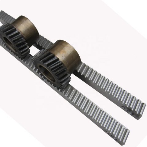
exists steel core inside the nylon gear rack.You can find two objects offered. There are actually 4 eye(4 bracket is light variety) and six eyes(six brackets is heavy kind).Every single piece of nylon gear rack with screw set
Producer supplier exporter of gear rack
We exported gear rack in huge amount to Europe, America, Australia, Brazil, South Africa, Russia and so forth. There is conventional gear rack obtainable as well as particular gear rack as per your drawing or samples. Our gear racks created by CNC machines
There is certainly many sizes of steel gears rack for sliding door also. M4 8?¨¢30, M4 9?¨¢30, M4 10?¨¢30, M4 11?¨¢30, M4 12?¨¢30, M4 20?¨¢20, M4 22?¨¢22, M6 30?¨¢30 and so on
For M4 8?¨¢30, M4 9?¨¢30, M4 10?¨¢30, M4 11?¨¢30, M4 12?¨¢30, 1M length have three bolt,nut, washer sets and every single 4pcs or 6pcs packed into carton box and after that put into steel pallet. For M4 8?¨¢30, M4 9?¨¢30, M4 10?¨¢30, M4 11?¨¢30, M4 12?¨¢30, 2M length have four bolt,nut, washer sets.
We are able to also supply the sliding gate component this kind of as sliding door pulley, wheel, roller and so on. Please kindly test and allow me know your detail request
In case you require 2M or 3M, or every other length, we are able to create as per your requests
Nearly all of our buyer will send us drawing and we are able to generate as per your drawing or sample.
We produce Module M1-M8 racks, CP and DP British regular racks. The utmost length of your rack is 2 meters. Our merchandise have been extensively used in several fields this kind of as automatic doors, window openers, engraving machines, lifters, escalators, automated warehousing, meals machinery, power resources, machine resources, precision transmission, etc.

We exported gear rack in major amount to Europe, America, Australia, Brazil, South Africa, Russia etc. There may be regular gear rack offered as well as distinctive gear rack as per your drawing or samples. Our gear racks generated by CNC machines.

Our gear racks are used for window machine, engraving machine, lift machine, opener rack, CNC machine, car, industrial usage so on.
one) Our gear rack is produced as per DIN specifications by CNC machine
two) The pressure angle: 20??/14.5??
3) Module: M0.4-M36/DP1-DP25
4) The utmost length is often 3500mm
five) The materials is often Q235, C45, SS304, SS316L, aluminum, copper, nylon and so on.
Our gear racks are employed for window machine, engraving machine, lift machine, opener rack, CNC machine, automobile, industrial usage so on.
Industrial Gear Rack
Lorem ipsum dolor sit amet, consectetur adipiscing elit, sed do eiusmod tempor incididunt ut labore et dolore magna aliqua.

We are able to also supply Building lift gear rack,American typical gears racks,steel gear rack,helical gear rack,versatile gear racks,energy steering rack,steering gear rack ,stainless steel gear rack ,round rack gear ,nylon gear rack ,spur gear rack ,boston gear rack ,audia gear rack ,gears racks ,rack and pinion gear
1. Wealthy business working experience due to the fact 1988.
two. Broad organize merchandise line, together with plastics sheet/rod/parts/accessories: MC NYLON, OIL NYLON, POM, UHMW-PE, PU, PETP, Pc, PTFE, PVDF, PPS, PEEK, PAI, PI, PBI ect.
three. Manufacture, layout and processing services as per your demand
1. Fantastic Tensile strength;
2. Large influence and notching effect strength;
three. High heat deflection temperature ;
four. Large power and stiffness;
five. Superior glide and limp residence characters;
six. Great chemical stability against organic solvents and fuels;
7. Resistant to thermal aging (applicable temperature amongst -50??C and 110??C;
eight. Size alternation by humidity absorption should be deemed;

Shaft sleeve, bearing bush, lining, lining plate, gear;
Worm gear, roller copper manual rail, piston ring, seal ring, slide block;
Spheric bowl, impeller, blade, cam, nut, valve plate,
Pipe, stuffing box, rack, belt pulley, pump rotor, and so on.rack pinion gear for elevator in stockoperator Steel and Nylon gear rack SPUR GEAR RACK AND PINION nylon gear rack iron gear rack We warmly welcome customers each at your house and abroad to contact us to negotiate organization, exchange details and cooperate with us.

ep

November 19, 2020

IN CNC GEAR Manufacturing PLANT, In excess of Ten OF GEARS Making LINES:
Gear turning,hobbing,shaving,shaping,grinding,slotting,
broaching , we?¡¥ve manufactured significant investment..

Our substantial precision tools can maintain a high high-quality prodcuts.CAN DO All the HEATING Process: CARBURIZING/CARBONITRIDING/QUENCHING/NORMALIZING/ANNEALING/REHEATING
two sets of UBE series multi-purpose chamber(IQ) Japan furnace;
2 sets of German Ipsen environment furnace lines.

9 ton of steel ability for heat treatment a day.
Minimal CARBON STEEL METAL GEARS Small,Modest STEEL METAL SPUR GEARS!
From uncomplicated 2-axis turning to 7-axis, turn-mill-drill CNC Swiss-type machines, we are outfitted with a total line of CNC products in the following manufactures:
molding machines/ stamping machines
automatic lathe machines/ spring machines.
Surface: as your requirement
OUR CLEANSES
one.Material:C 45# steel ,stainless steel or other needed resources.
2.Sprockets might be created in accordance the customer?¡¥s drawings
Our key solutions: Ultra high molecular bodyweight polyethylene, MC nylon, PA6, POM, HDPE, PP,PU, Computer, PVC, ABS, ACRYLIC,PTFE, PEEK, PPS,PVDF.
three.Heat treatment method: Hardening and Tempering, Substantial Frequency Quenching, Carburizing Quenching and so on in accordance the requirements..

4. Inspection: All goods are checked and examined extensively during each operating procedure and right after production are going to be reinspected.
Gear transmission refers to the gadget that transmits movement and electrical power from the gear pair. It’s essentially the most widely applied mechanical transmission process in modern-day tools. Its transmission is much more accurate, large efficiency, compact structure, dependable operation and extended support life.

Our gears could be heat treated, hardened, oil immersed in accordance to client requires.

The gear is broadly employed in industry, car, power tools, motor, bicycle, electrombile.
Large PRECISION Custom SPUR HELICAL GEAR
Spur gears are extensively accepted as the most effective form of gearing alternative, when the application of transmitting electrical power and uniform rotary movement from a single parallel shaft to a further is required. Determined through the center distance, spur gears generate a regular functioning speed drive. This drive velocity is often decreased or improved through the variable amount of teeth that exist in the driving gear.
Style: BEVEL GEAR
Manufacturing Approach: Lower Gear
Toothed Portion Form: Bevel Wheel
Major Buyer: Electric tool factory
Export Markets: International
Small PINION STEEL DOUBLE SPUR GEAR
Zn-plating, Ni-plating, Cr-plating, Tin-plating, copper-plating, the wreath oxygen resin spraying, the heat disposing, hot-dip galvanizing,
ELECTROPLATING, ANODIZING Etc.
Black oxide coating, painting, powdering, color zinc-plated, blue black zinc-plated, rust preventive oil, titanium alloy galvanized, silver plating, plastic,We are able to make customers?¡¥ satisfactory merchandise in accordance for the samples or drawings provided by clients. For the completion of the merchandise, we also need to have to learn his material, heat remedy prerequisites and surface treatment method needs. We’re a factory with 40 years of manufacturing practical experience, welcome to talk to.
we use the most up-to-date machining technology by using a wide assortment of abilities to meet your demands. Our manufacturing services include things like 3-5 axis milling, lathes, grinding, and so on, and state of your artwork metrology. With these machines, we produce complicated elements in the most productive and accurate way. Our manufacturing abilities let us to produce your aspect from prototype to mass production to the most exact of jobs.
gear box,gearbox,automatic gearbox,gearbox parts,gearbox repairs,steering gear box,reduction gearbox,worm gear,motor gearbox,car or truck gearbox,gearbox store,worm gear box,gearbox producers,box gear,planetary gear box,tiny gearbox,helical gearbox,dc gear motor,gear motor,gear reducer,helical gear box,vehicle gear box,gearbox gears,transmission gearbox,reduction gear box,planetary gear,gearbox transmission,car or truck transmission,applied gearbox for sale,worm gear motor,applied gearbox,worm gear reducer,transmission gears,planetary gear reducer,substitute gearbox,mini gearbox

ep

November 18, 2020

PTO is often a splined drive shaft that is usually placed on tractors or is often utilised to supply energy backup to a separate machine.

The PTO shafts that we present comprises of two carden joints and telescopic couplings. Tractor side and apply side would be the two ends of those shafts. The employ side features a shear bolt sort yoke and includes security guards.
one, Material: Carbon steel/ stainless steel/ aluminum alloy/ copper/bronze/iron/etc.

two, OEM or as per sample or drawing

three, Surface: Blacking, Polishing, Anodize, Chrome plating, Zinc plating, Nickel plating, Tinting, Power coating etc.

four, Approach: Forging, Stamping, Machining, Metalworking, Sheet Metal Bending, Surface Treatment method, Heat Remedy, Gridding, Milling, wire EDM, Linear Cutting and so on.

five, Precision: OEM/ODM is available
The electrical power take-off (PTO) can be a sophisticated mechanism, permitting implements to draw power through the engine and transmit it to another application. It functions being a mechanical gearbox which may be mounted over the vehicle?¡¥s transmission.
CHINA FACTORY LARGEBRASS MILLING AND ALUMINUM CASTING MOLDS Manufacturer
We’re the producer to provide Japanese tractor spare components,specially for kubota,iseki,yanmar,and so forth.
We’re supplying and exporting Japanese tractor parts since the following models
¡§C Kubota model: B5000, B7000, B1400, B1600
¡§C YM model: YM F14, YM1100, YM F1401/1901,YM F35
¡§C Iseki model: TX1300, TX1410,TU1400-1500
UNIVERSAL JOINT MECHANICAL COMPORENTS MACHINE TRACTOR PTO SHAFT Parts UNIVERSAL JOINT
Tubes or Pipes

We?¡¥ve already received Triangular profile tube and Lemon profile tube for every one of the series we present.

And we have some star tube, splined tube as well as other profile tubes but only to get a selected sizes.
We specializing inside the production of Agricultural Gearbox, PTO Shafts, Sprockets, Fluid Coupling, Worm Gear Reducers, Gears and racks, Roller Chains, Sheave and Pulleys, Planetary Gearboxes, Timing Pulleys, Shaft Collars and more.
five End yokes

We’ve received 13 varieties of splined yokes and 8 styles of plain bore yokes. I’ll propose the normal form for the reference.

You may also send drawings or photos to us when you can not obtain your item in our catalog.

six Security products or clutches

I will attach the facts of safety devices for your reference. We have currently have Free wheel (RA), Ratchet torque limiter(SA), Shear bolt torque limiter(SB), 3types of friction torque limiter (FF,FFS,FCS) and overrunning couplers(adapters) (FAS).

seven For any other much more distinctive prerequisites with plastic guard, connection system, colour of painting, bundle, and so on., please truly feel no cost to allow me know.
The Gearboxes are built for connecting gear pumps to farm tractor energy get offs (PTO). Output speed of electrical power get offs is 540rpm which could be compared with the suitable working speeds of hydraulic pumps. Distinct input operating speeds may also be ideal,presented that the PTO gearbox output pace will not exceed 3000 rpm.
Housing
Created in shell-cast aluminum or in substantial mechanical resistance cast iron.
Torques
The torque figures stated inside the technical charts of every one of the PTO Gearboxes refer to continuous duty cycles. Torques below intermittent doing work problems could be exceeded by 20%.
Maintenance
Please verify the oil level via the unique oil window every 50 hrs. Working temperatures need to not exceed 120 degrees celcius underneath continuos duty cycle.
one. Tubes or Pipes
We’ve currently got Triangular profile tube and Lemon profile tube for all the series we give.
And we have now some star tube, splined tube together with other profile tubes necessary by our customers (for a specified series). (Please notice that our catalog doesnt contain each of the objects we produce)
If you would like tubes other than triangular or lemon, please present drawings or photos.

two.Finish yokes
We’ve acquired a number of styles of quick release yokes and plain bore yoke. I’ll suggest the usual type for the reference.
You’ll be able to also send drawings or pics to us in the event you are not able to uncover your item in our catalog.

three. Security devices or clutches
I will attach the information of security units for your reference. We’ve previously have Absolutely free wheel (RA), Ratchet torque limiter(SA), Shear bolt torque limiter(SB), 3types of friction torque limiter (FF,FFS,FCS) and overrunning couplers(adapters) (FAS).

4.For almost any other additional distinctive necessities with plastic guard, connection approach, colour of painting, package deal, and so on., please truly feel free to let me know.

Functions:
one. We have been specialized in designing, manufacturing drive shaft, steering coupler shaft, universal joints, which have exported for the USA, Europe, Australia and so on for a long time
2. Application to all varieties of general mechanical situation
three. Our items are of higher intensity and rigidity.
four. Heat resistant & Acid resistant
5. OEM orders are welcomed
The Gearboxes are created for connecting gear pumps to farm tractor electrical power get offs (PTO).Output pace of energy take offs is 540rpm which can be in contrast together with the proper operating speeds of hydraulic pumps.Distinctive input operating speeds can also be appropriate,presented that the PTO gearbox output pace will not exceed 3000 rpm.

Gears
Manufactured in Steel UNI 18 PCR M03.Stub teeth guarantee very higher resistance and run very quietly.

Shafts
Manufactured in steel UNI 16 CRN4.They are coupled with splined gears and are made to stand the torque values stated from the catalogue.

Lubrication
90 gear oil must be put during the pto gearbox prior to use, change the oil after the first 60-80 hrs and then every 12 months or 1500 hours which ever falls first.

Servicing
Please test the oil degree via the specific oil window each and every 50 hrs.Working temperatures need to not exceed 120 degrees celcius underneath continuos duty cycle.

ep

November 17, 2020

Producer supplier exporter of bush chains

We specializing within the manufacturing of Agricultural Gearbox, PTO Shafts, Sprockets, Fluid Coupling, Worm Gear Reducers, Gears and racks, Roller Chains, Sheave and Pulleys, Planetary Gearboxes, Timing Pulleys, Shaft Collars and even more.
Taper Lock Pulley V Belt Pulley
We supply substantial good quality Taper Lock Pulley V Belt Pulley in aggressive price
v pulley, v belt pulleys, taper lock pulley,v belt pulleys ,v pulley,v groove pulleys,v groove belt pulley,taper lock pulley,taper lock v belt pulleys,taper lock bushing pulley,taper lock pulleys/ taper bore pulley,significant v belts pulley,double v belts pulley,cast iron v belt pulleys belt pulley,variable velocity v belt pulley,v belt pulley split pulley,cast iron v belts pulley
V-BELT PULLEY INTRODUCE:
V- belt pulley of various types ( according to sort and width of belts). The materials employed is cast iron EN-GJL-250 UNI EN 1561, and for only several varieties it truly is steel C45 E UNI EN 10083-1. They’ve got a compact prebore that will be machined in accordance with customers?¡¥ demands. Additionally by far the most typical sorts can be found also with taperlock bore.
V BELT PULLEY Specifications
a) Vbelt pulley for taper bushing: SPZ, SPA, SPB, SPC
b) Adjustable pace V-belt pulleys and variable pace pulleys c) Flat belt pulleys and conveyor belt pulleys
?¡è AMERICAN Normal:
a) vpulley sheaves for taper bushing: 3V, 5V, 8V
b) Sheaves for QD bushings: 3V, 5V, 8V
c) Sheaves for split taper bushing: 3V, 5V, 8V
?¡è We will Offer THE RANG Size DIAMETER 62MM~2000MM
d) Sheaves for 3L, 4L or a, and 5L or B belts: AK, AKH,2AK, 2AKH, BK, BKH,2BK, 2BKH, 3BK e) Adjustable sheaves: poly V-pulley, multi-pitch H, L, J, K and M
High quality Timing Pulley Light Fat Industrial Nylon Plastic Pulley V Belt Pulley
one.Materials: Aluminium alloy,Carton steel, Cast iron, Stainless steel timing belt pulleys
two.Surface treament: Anodizing, Blackening, Zinc Plating, Phosphatiing
three. Teeth Amount from 9 to 216; O.D. from 10mm to 1000mm;
4. Timing belt pulleys MXL, XL, L, H and XH; T2.5, T5, T10, AT5,AT10; 3M,5M,8M and 14M S3M, S5M, S8M, 14MGT, 8MGT, RPP8M
5. Taper bush and polit bores
6. Timing pulley bar 3M,5M,8M,MXL,XL,L T2.5 T5 T10 AT5 and AT10
one) Sound style, ideal for heavy lifting.
2) The bearing housing and steel tube are assembled and welded which has a concentric automatic.
automobile
four) The bearing finish is constructed to ensure the roller shaft and bearing is often firmly connected.
air compressors
six) Roller and supporting components/materials are produced to DIN/ AFNOR/ FEM/ ASTM/ CEMA standard.
belt conveyor drive drum pulley
About roller,we will make gravity conveyor roller,steel conveyor roller,driving roller,light middle duty conveyor roller,o-belt tapered sleeve roller,gravity tapered roller,polymer sprocket roller and so on. Extra facts, please make contact with us.
Is usually used for tractors
3) Cutting in the steel tube and bearing is performed together with the use of a digital car device/machine/equipment..
backyard cutter
5) Fabrication with the roller is effected by an car device and 100% examined for its concentricity.
welcome your inquiries
7) The casing is produced with highly composite, anti corrosive alloy.
one) European requirements :
a) V-belt pulley for taper bushing: SPZ, SPA, SPB, SPC; as much as 10 grooves

b) Adjustable pace V-belt pulleys and variable velocity pulley

c) Flat belt pulleys and conveyor belt pulleys

two) American requirements:

a) Sheaves for taper bushing: 3V, 5V, 8V

b) Sheaves for QD bushings: 3V, 5V, 8V

c) Sheaves for split taper bushing: 3V, 5V, 8V

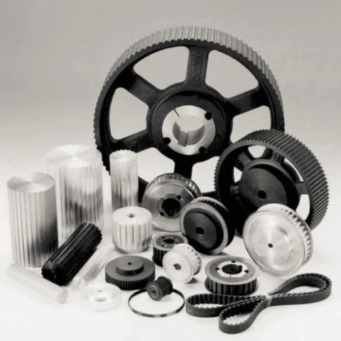
d) Sheaves for 3L, 4L or perhaps a, and 5L or B belts: AK, AKH, 2AK, 2AKH, BK, BKH,2BK, 2BKH, 3BK

e) Adjustable sheave: poly V-pulley, multi-pitch H, L, J, K and M
Why Pick Us
1) Expertise in casting for above 15 many years and served customers all about the entire world.
2) Standard material in accordance with technical drawing
3)Stable excellent
4) On-time delivery
five) Aggressive cost and excellent support
6) Optimistic buyer suggestions from domestic and international industry
seven) International advanced-level tools for instance CNC, numerical lathes, furnance, welding
products, CMM and detect &testing gear we made use of to make certain our product?¡¥s high-quality.
8) OEM service, your demand is our pursued.
9) ISO9001:2008 and TS16949 excellent control
10) Normal: ASTM BS DIN etc

ep

November 16, 2020

Bush Chains
As among major motor coupling suppliers, suppliers and exporters of mechanical goods, We offer you bush chains and many other goods.
Manufacturer supplier exporter of bush chains
We specializing in the manufacturing of Agricultural Gearbox, PTO Shafts, Sprockets, Fluid Coupling, Worm Gear Reducers, Gears and racks, Roller Chains, Sheave and Pulleys, Planetary Gearboxes, Timing Pulleys, Shaft Collars and even more.
We have now exported our solutions to consumers all around the planet and earned a superb reputation since of our superior solution excellent and after-sales support.
We warmly welcome prospects the two at your home and abroad to make contact with us to negotiate enterprise, exchange information and cooperate with us.
we’re one particular expert chain factory ,generating the two standard roller chains and nonstandard chains,A and B series roller chain,straight side roller chain,H series of roller chain, motocycle chain ,other roller chain .
Zinc-plated,Nickel-plated,Docromet-plated etc.Comply with all the conventional of ANSI,ISO,DIN,BSetc.and in addition with distinct attachment. High-quality could be guaranteed!
Our solutions have passed ISO:9001 good quality management procedure and stand the finish users?¡¥ ordeal. We dedicate ourselves to manufacture the high-quality products with aggressive charges, we know the industries properly, therefore from design to materials assortment, till manufacturing method is up to the higher typical, meanwhile our planning crew and international group will assure the punctual delivery.
Timing Bush Chains for Car Engine
1. Material: Stainless steel / Alloy steel / Manufactured to purchase
2. Surface Remedy: Zinc-Plated / Nickel-Plated / Shot Peening / Blackening
3. Chain Type: Roller chains, Drive chains,Conveyor Chains, Hollow Pin Chains,Welded chains, Steel Pin Chains, Palm oil chains,Sugar Mill Chains.ect.
Transmission Precision Bush Chains
A lifting chain is rigging equipment utilized with hoists, cranes, and winches in material handling applications. An arrangement identified as a chain sling is usually made use of because the lifting part connecting the hoisting gadget to the load. A chain sling consists of a master link and one or far more chain legs with hooks.
Transmission Precision Roller and Bush Chains
Made use of industrial transmission roller chains;Industrial and agricultural machinery, which include conveyors,wire¡§C and tube¡§Cdrawing machines, printing presses, vehicles, motorcycles, and bicycles.It consists of a series of short cylindrical rollers held with each other by side links.It is an easy, dependable, and productive indicates of electrical power transmission.
Excellent orientation: Above the typical, mostly exported to USA, Europe, Asia etc.
Strictly in accordance: ISO/ANSI/DIN regular.
Price tag orientation: Price-performance ratio is incredibly higher.
Stainless Steel Hollow Pin Bush Chains Conveyor Chain Roller transmission bush double flex chain Side Bow Chain The Sleeve Chain/ Bush Chain/motorcycle chain high strength bucket elevator conveyor bush roller chain
We are skilled supplier of chains
Multi strand sizes available; as much as 5 strand, for choose dimension normal attachment readily available
10.Chains from 04b~16b are with spring clip, other are riveted; cottered style
is accessible for dimension 80 to 240
Stainless steel chain and nickel plated chains is obtainable; special design also offered
(i.e., oven conveyor) and we are able to create as per material your requests, commonly stainless steel chains materials is SS304, when you require SS316 or SS316L etc. it’s accessible too
This bush chain with a reduced quantity of elements, has proved to be particularly productive in high duty, higher abrasion application where lubrication is just not possible. Our steel bush chains are proving functionality in mill duty centrifugal discharge elevators inside the more difficult applications encountered while in the cement market.

China Best Sales China Factory Wholesale Maintenance Free Long Life Steel Reducer Gearbox small cycloidal gearbox

Product Description

Product Description

China Factory wholesale maintenance free long life steel reducer Gearbox

HangZhou Fubao Electromechanical Technology Co., Ltd.WF series steel reducer Gearbox for 5 axis machining center developed and manufactured by WEITENSTAN together with German and ZheJiang technicians for many years.

High precision miniature cycloidal gearbox has the characteristics of smaller, ultra-thin, lightweight and high rigidity, anti-overload and high torque. With good deceleration performance, smooth operation and accurate positioning can be achieved. Integrated design, can be directly connected with the motor, to achieve high precision, high rigidity, high durability and other advantages. It is designed for high speed ratio, high geometric accuracy, low motion loss, large torque capacity and high stiffness applications. The compact design (minimum OD ≈40mm, currently the world’s smallest precision cycloidal pin-wheel reducer) allows it to be installed in limited Spaces.

The design of WEITENSTAN high-precision reducers is based on a new reduction principle and newly developed radial and axial output bearings. The result is a new generation of power transmission systems. The new drive concept allows WEITENSTAN gear units to be used directly in the gears of robot joints, rotary tables and various transport systems.

WEITENSTAN high-precision reducers are designed for applications requiring large speed ratios, high precision, low-loss motion, high torque capacity, and high rigidity. At the same time, they are compact in design, can be installed in limited spaces, and have small inertia.

Reducer drawings

Detailed Photos


Product Advantage

China Factory wholesale maintenance free long life steel reducer Gearbox

advantages:

1, fine precision cycloidal structure

Ultra flat shape is achieved through differential reduction mechanism and thin cross roller bearing, contributing to the compact size of the equipment. The combination of small size and unmatched superior parameters achieves the best combination of performance, price and size (high cost performance).


2. Excellent accuracy (transmission loss ≤1 arcmin)

Through the complex meshing of precision cycloid gear and high precision roller pin, higher transmission accuracy is achieved while maintaining small size and high speed ratio.


3, high rigidity

Increase the mesh rate to disperse the load, so the rigidity is high.


4. High overload capacity

It maintains trouble-free operation under abnormally low noise and vibration conditions while ensuring excellent overturning and torsional stiffness parameters. Integrated axial radial cross roller bearings, high load capacity and overload capacity of the reducer, can ensure users to provide a variety of temperature range of applications.


5, the motor installation is simple

Electromechanical integration design, can be directly connected with the motor, any brand of motor can be installed directly, without adding any device.


6. Maintenance free

Seal grease to achieve maintenance free. No refueling, no mounting direction restrictions.


7, stable performance

The manufacturing process of high wear-resistant materials and high precision parts has been certified by ISO9000 quality system, which guarantees the reliable operation of the reducer.


Product Classification


WF Series
High Precision Miniature Reducer

WF series is a high precision micro cycloidal reducer with flange, which has a wide range of applications. This series of reducers includes precise reduction mechanisms and radial – axial roller bearings. The unique design allows load to act directly on the output flange or housing without additional bearings. WF series reducer is characterized by module design, can be installed through the flange motor and reducer, belongs to the motor directly connected reducer.

WFH Series
High Precision Miniature Reducer

WFH series is a hollow form of high precision miniature cycloidal reducer, wire, compressed air pipeline, drive shaft can be through the hollow shaft, non-motor direct connection type reducer. The WFH series is fully sealed, full of grease and includes precise deceleration mechanism and radial – axial roller bearings. The unique design allows load to be acted directly on the output flange or housing without additional bearings.

WR Series
high-precision corner reducer

The WR series is a flange output corner reducer. Like the WF and WFH series, it is a high-precision reducer (backlash less than 1 arc.min), and the level 2 can also be within 1 arc.min, which is higher than other types. Corner type reducer. It can replace the harmonic drive reducer, and its life and rigidity are more than 3 times that of the harmonic.


Product Parameters

Size reduction ratio Rated output moment Allowable torque of start and stop Instantaneous allowable moment Rated input speed Maximum input speed Tilt stiffness Torsional stiffness No-load starting torque Transmission accuracy Error accuracy Moment of inertia Weight
  Axis rotation Shell rotation Nm Nm Nm rpm rpm Nm/arcmin Nm/arcmin Nm arcmin arcmin kg-m² kg
WF07 21 20 15 30 45 3000 6000 6 1.1 0.12 P1≤±1           P2≤±3 P1≤±1           P2≤±3 0.52 0.42
41 40 0.11 0.47
WF17 21 20 50 100 150 3000 6000 28 6 0.21 P1≤±1           P2≤±3 P1≤±1           P2≤±3 0.88 0.85
41 40 0.18 0.72
61 60 0.14 0.69
WF25 21 20 110 220 330 3000 5500 131 24 0.47 P1≤±1           P2≤±3 P1≤±1           P2≤±3 6.12 2
31 30 0.41 5.67
41 40 0.38 4.9
51 50 0.35 4.56
81 80 0.31 4.25
WF32 25 24 190 380 570 3000 4500 240 35 1.15 P1≤±1           P2≤±3 P1≤±1           P2≤±3 11 4.2
31 30 1.1 10.8
51 50 0.77 9.35
81 80 0.74 8.32
101 100 0.6 7.7
WF40 25 24 320 640 960 3000 4000 377 50 1.35 P1≤±1           P2≤±3 P1≤±1           P2≤±3 13.2 6.6
31 30 1.32 12.96
51 50 0.92 11.22
81 80 0.81 9.84
121 120 0.72 8.4

Installation Instructions


Company Profile


Q: Speed reducer grease replacement time
A: When sealing appropriate amount of grease and running reducer, the standard replacement time is 20000 hours according to the aging condition of the grease. In addition, when the grease is stained or used in the surrounding temperature condition (above 40ºC), please check the aging and fouling of the grease, and specify the replacement time.

Q: Delivery time
A: Fubao has 2000+ production base, daily output of 1000+ units, standard models within 7 days of delivery.

Q: Reducer selection
A: Fubao provides professional product selection guidance, with higher product matching degree, higher cost performance and higher utilization rate.

Q: Application range of reducer
A: Fubao has a professional research and development team, complete category design, can match any stepping motor, servo motor, more accurate matching.


Shipping Cost:

Estimated freight per unit.


To be negotiated
Application: Motor, Machinery, Agricultural Machinery
Hardness: Hardened Tooth Surface
Installation: Horizontal Type

helical gearbox

A Mathematical Model of a Cycloid Gearbox

Having a gearbox with a cycloidal rotor is an ideal design for a car or any other vehicle, as the cycloidal design can reduce the amplitude of vibration, which is a key component in car performance. Using a cycloidal gearbox is also a great way to reduce the amount of friction between the gears in the gearbox, which can help to reduce noise and wear and tear. A cycloidal gearbox is also a very efficient design for a vehicle that needs to perform under high loads, as the gearbox can be very robust against shock loads.

Basic design principles

cycloidal gearboxes are used for precision gearing applications. Cycloidal drives are compact and robust and offer lower backlash, torsional stiffness and a longer service life. They are also suitable for applications involving heavy loads.
Cycloidal drives are compact in size and provide very high reduction ratios. They are also very robust and can handle shock loads. Cycloidal drives are ideally suited to a wide range of drive technologies. Cycloidal gears have excellent torsional stiffness and can provide a transmission ratio of 300:1. They can also be used in applications where stacking multiple gear stages is not desired.
In order to achieve a high reduction ratio, cycloidal gears must be manufactured extremely accurately. Cycloidal gears have a curved tooth profile that removes shear forces at any point of contact. This provides a positive fit for the gear disc. This profile can be provided on a separate outer bushing or as an internal gear profile insert.
Cycloidal drives are used in marine propulsion systems, where the load plate rotates around the X and Y axis. The plate is anchored by a threaded screw hole arranged 15mm away from the center.
A secondary carrier body is used in a cycloidal gearbox to support the load plate. The secondary carrier body is composed of a mounting carrier body and a secondary carrier disc.

Low friction

Several studies have been conducted to understand the static problems of gears. In this paper, we discuss a mathematical model of a low friction cycloidal gearbox. This model is designed to calculate various parameters that affect the performance of the gearbox during production.
The model is based on a new approach that includes the stiction effect and the nonlinear friction characteristic. These parameters are not covered by the conventional rule of thumb.
The stiction effect is present when the speed direction is changed. During this time, the input torque is required to prevail over the stiction effect to generate movement. The model also enables us to calculate the magnitude of the stiction effect and its breakaway speed.
The most important thing is that the model can be used to improve the dynamic behavior of a controlled system. In this regard, the model has a high degree of accuracy. The model is tested in several quadrants of the gearbox to find the optimum stiction breakaway speed. The simulation results of the model show that this model is effective in predicting the efficiency of a low friction cycloidal gearbox.
In addition to the stiction model, we also studied the efficiency of a low friction cycloidal reducer. The reduction ratio of this gearbox was estimated from the formula. It is found that the ratio approaches negative infinity when the motor torque is close to zero Nm.

Compact

Unlike standard planetary gears, cycloidal gearboxes are compact, low friction and feature virtually zero backlash. They also offer high reduction ratios, high load capacity and high efficiency. These features make them a viable option for a variety of applications.
Cycloid disks are driven by an eccentric input shaft. They are then driven by a stationary ring gear. The ring gear rotates the cycloidal disk at a higher rate. The input shaft rotates nine times to complete a full rotation. The ring gear is designed to correct the dynamic imbalance.
CZPT cycloidal gearheads are designed for precision and stable operation. These reducers are robust and can handle large translocations. They also offer high overload protection. They are suitable for shock wave therapy. CZPT gearheads are also well suited for applications with critical positioning accuracy. They also require low assembly and design costs. They are designed for long service life and low hysteresis loss.
CZPT cycloidal reducers are used in a variety of industrial applications, including CNC machining centers, robot positioners and manipulators. They offer a unique design that can handle high forces on the output axis, and are especially suitable for large translocations. These gearheads are highly efficient, reducing costs, and are available in a variety of sizes. They are ideal for applications that require millimetre accuracy.

High reduction ratios

Compared to other gearboxes, cycloidal gearboxes offer high reduction ratios and small backlash. They are also less expensive. Cycloid gearboxes can be used in a variety of industries. They are suitable for robotic applications. They also have high efficiency and load capacity.
A cycloidal gearbox works by rotating a cycloidal disc. This disc contains holes that are bigger than the pins on the output shaft. When the disc is rotated, the output pins move in the holes to generate a steady output shaft rotation. This type of gearbox does not require stacking stages.
Cycloid gearboxes are usually shorter than planetary gearboxes. Moreover, they are more robust and can transmit higher torques.
Cycloid gearboxes have an eccentric cam that drives the cycloidal disc. The cycloidal disc advances in 360deg/pivot/roller steps. It also rotates in an eccentric pattern. It meshes with the ring-gear housing. It also engages the internal teeth of the ring-gear housing.
The number of lobes on the cycloidal disc is not sufficient to generate a good transmission ratio. In fact, the number of lobes must be less than the number of pins surrounding the cycloidal disc.
The cycloidal disc is rotated by an eccentric cam that extends from the base shaft. The cam also spins inside the cycloidal disc. The eccentric motion of the cam helps the cycloidal disc rotate around the pins of the ring-gear housing.helical gearbox

Reducing amplitude of the vibration

Various approaches to reducing amplitude of the vibration in a cycloidal gearbox have been studied. These approaches are based on the kinematic analysis of gearbox.
A cycloidal gearbox is a gearbox that consists of bearings, gears, and an eccentric bearing that drives a cycloidal disc. This gearbox has a high reduction ratio, which is achieved by a series of output shaft pins that drive the output shaft as the disc rotates.
The test bench used in the studies has four sensors. Each sensor acquires signals with different signal processing techniques. In addition, there is a tachometer that acquires variations in rotational velocity at the input side.
The kinematic study of the robotic gearbox was performed to understand the frequency of vibrations and to determine whether the gearbox is faulty. It was found that the gearbox is in healthy operation when the amplitude of the x and y is low. However, when the amplitude is high, it is indicative of a malfunctioning element.
The frequency analysis of vibration signals is performed for both cyclostationary and noncyclostationary conditions. The frequencies that are selected are those that appear in both types of conditions.

Robust against shock loads

Compared to traditional gearboxes, cycloidal gearboxes have significant benefits when it comes to shock loads. These include high shock-load capacity, high efficiency, reduced cost, lower weight, lower friction, and better positioning accuracy.
Cycloid gears can be used to replace traditional planetary gears in applications where inertia is important, such as the transportation of heavy loads. They have a lighter design and can be manufactured to a more compact size, which helps reduce cost and installation expense. Cycloid gears are also able to provide transmission ratios of up to 300:1 in a small package.
Cycloid gears are also suitable for applications where a long service life is essential. Their radial clamping ring reduces inertia by up to 39%. Cycloid gears have a torsional stiffness that is five times higher than that of conventional planetary gears.
Cycloid gearboxes can provide significant improvements in concrete mixers. They are a highly efficient design, which allows for important innovations. They are also ideal for servo applications, machine tools, and medical technology. They feature user-friendly screw connections, effective corrosion protection, and effective handling.
Cycloid gears are especially useful for applications with critical positioning accuracy. For example, in the control of large parabolic antennas, high shock load capacity is required to maintain accuracy. Cycloid gears can withstand shock loads up to 500% of their rated torque.helical gearbox

Inertial effects

Various studies have been conducted to investigate the static problems of gears. However, there is still a need for a proper model to investigate the dynamic behaviour of a controlled system. For this, a mathematical model of a cycloidal gearbox has been developed. The presented model is a simple model that can be used as the basis for a more complex mechanical model.
The mathematical model is based on the cycloidal gearbox’s mechanical construction and has a nonlinear friction characteristic. The model is able to reproduce the current peaks and breaks at standstill. It also considers the stiction effect. However, it does not cover backlash or torsional stiffness.
This model is used to calculate the torque generating current and the inertia of the motor. These values are then compared with the real system measurement. The results show that the simulation results are very close to the real system measurement.
Several parameters are considered in the model to improve its dynamic behaviour. These parameters are calculated from the harmonic drive system analysis. These are torque-generating current, inertia, and the contact forces of the rotating parts.
The model has a high level of accuracy and can be used for motor control. It is also able to reproduce the dynamic behaviour of a controlled system.
China Best Sales China Factory Wholesale Maintenance Free Long Life Steel Reducer Gearbox   small cycloidal gearboxChina Best Sales China Factory Wholesale Maintenance Free Long Life Steel Reducer Gearbox   small cycloidal gearbox
editor by CX 2023-05-26

China OEM China Reducer Factory Produces High-Precision Gearboxes for Walking Training Machines cycloidal gearbox design

Product Description

Product Description

China reducer factory produces high-precision gearboxes for walking training machines
WF series  gearboxes  for 5 axis machining center developed and manufactured by WEITENSTAN together with German and ZheJiang technicians for many years.

High precision miniature cycloidal gearbox has the characteristics of smaller, ultra-thin, lightweight and high rigidity, anti-overload and high torque. With good deceleration performance, smooth operation and accurate positioning can be achieved. Integrated design, can be directly connected with the motor, to achieve high precision, high rigidity, high durability and other advantages. It is designed for high speed ratio, high geometric accuracy, low motion loss, large torque capacity and high stiffness applications. The compact design (minimum OD ≈40mm, currently the world’s smallest precision cycloidal pin-wheel reducer) allows it to be installed in limited Spaces.
 

Product Parameters

Size reduction ratio Rated output moment Allowable torque of start and stop Instantaneous allowable moment Rated input speed Maximum input speed Tilt stiffness Torsional stiffness No-load starting torque Transmission accuracy Error accuracy Moment of inertia Weight
  Axis rotation Shell rotation Nm Nm Nm rpm rpm Nm/arcmin Nm/arcmin Nm arcmin arcmin kg-m² kg
WF07 21 20 15 30 45 3000 6000 6 1.1 0.12 P1≤±1           P2≤±3 P1≤±1           P2≤±3 0.52 0.42
41 40 0.11 0.47
WF17 21 20 50 100 150 3000 6000 28 6 0.21 P1≤±1           P2≤±3 P1≤±1           P2≤±3 0.88 0.85
41 40 0.18 0.72
61 60 0.14 0.69
WF25 21 20 110 220 330 3000 5500 131 24 0.47 P1≤±1           P2≤±3 P1≤±1           P2≤±3 6.12 2
31 30 0.41 5.67
41 40 0.38 4.9
51 50 0.35 4.56
81 80 0.31 4.25
WF32 25 24 190 380 570 3000 4500 240 35 1.15 P1≤±1           P2≤±3 P1≤±1           P2≤±3 11 4.2
31 30 1.1 10.8
51 50 0.77 9.35
81 80 0.74 8.32
101 100 0.6 7.7
WF40 25 24 320 640 960 3000 4000 377 50 1.35 P1≤±1           P2≤±3 P1≤±1           P2≤±3 13.2 6.6
31 30 1.32 12.96
51 50 0.92 11.22
81 80 0.81 9.84
121 120 0.72 8.4

product drawings

Detailed Photos

China reducer factory produces high-precision gearboxes for walking training machines

advantages:


1, fine precision cycloidal structure

Ultra flat shape is achieved through differential reduction mechanism and thin cross roller bearing, contributing to the compact size of the equipment. The combination of small size and unmatched superior parameters achieves the best combination of performance, price and size (high cost performance).


2. Excellent accuracy (transmission loss ≤1 arcmin)

Through the complex meshing of precision cycloid gear and high precision roller pin, higher transmission accuracy is achieved while maintaining small size and high speed ratio.


3, high rigidity

Increase the mesh rate to disperse the load, so the rigidity is high.


4. High overload capacity

It maintains trouble-free operation under abnormally low noise and vibration conditions while ensuring excellent overturning and torsional stiffness parameters. Integrated axial radial cross roller bearings, high load capacity and overload capacity of the reducer, can ensure users to provide a variety of temperature range of applications.


5, the motor installation is simple

Electromechanical integration design, can be directly connected with the motor, any brand of motor can be installed directly, without adding any device.


6. Maintenance free

Seal grease to achieve maintenance free. No refueling, no mounting direction restrictions.


7, stable performance

The manufacturing process of high wear-resistant materials and high precision parts has been certified by ISO9000 quality system, which guarantees the reliable operation of the reducer.
 

Product Classification

WF Series
High Precision Miniature Reducer

WF series is a high precision micro cycloidal reducer with flange, which has a wide range of applications. This series of reducers includes precise reduction mechanisms and radial – axial roller bearings. The unique design allows load to act directly on the output flange or housing without additional bearings. WF series reducer is characterized by module design, can be installed through the flange motor and reducer, belongs to the motor directly connected reducer.

WFH Series
High Precision Miniature Reducer

WFH series is a hollow form of high precision miniature cycloidal reducer, wire, compressed air pipeline, drive shaft can be through the hollow shaft, non-motor direct connection type reducer. The WFH series is fully sealed, full of grease and includes precise deceleration mechanism and radial – axial roller bearings. The unique design allows load to be acted directly on the output flange or housing without additional bearings.

WR Series
high-precision corner reducer

The WR series is a flange output corner reducer. Like the WF and WFH series, it is a high-precision reducer (backlash less than 1 arc.min), and the level 2 can also be within 1 arc.min, which is higher than other types. Corner type reducer. It can replace the harmonic drive reducer, and its life and rigidity are more than 3 times that of the harmonic.

Installation Instructions

Company Profile

FAQ

Q:Are you a factory or a trading company ? where is your office ?

A:We are a company integrating industry and trade.The company is located at No. 101, Building F, HangZhou Industrial Park, No. 1 CZPT Street, Xiaobian Community, Chang’an Town, HangZhou City.

Q: What are your main products?

A: We currently have self-developed and manufactured planetary gearboxes, rv reducers, cycloidal gearboxes, hollow rotating platforms, steering gears, couplings and other products. You can view the specifications of the above products on our website, you can send us an email or leave a message, and our technical consultants will choose the product that suits you according to your needs.

Q: What’s your delivery time?

A: Generally speaking, it takes 15-30 days for our regular standard products, and it takes longer for customized products. But we are very flexible about the delivery time, it will depend on the specific order.

Q: Delivery time

A: Fubao has 2000+ production base, daily output of 1000+ units, standard models within 7 days of delivery.

Q: Reducer selection

A: Fubao provides professional product selection guidance, with higher product matching degree, higher cost performance and higher utilization rate.

Q: Application range of reducer

A: Fubao has a professional research and development team, complete category design, can match any stepping motor, servo motor, more accurate matching.


Shipping Cost:

Estimated freight per unit.


To be negotiated
Application: Motor, Machinery, Agricultural Machinery, Humanoid Robot
Hardness: Hardened Tooth Surface
Installation: Any Direction
Customization:
Available

|

Customized Request

helical gearbox

Cyclone Gearbox Vs Involute Gearbox

Whether you’re using a cycloidal gearbox or an involute gearbox for your application, there are a few things you should know. This article will highlight some of those things, including: cycloidal gearbox vs involute gearbox, weight, compressive force, precision, and torque density.

Compressive force

Several studies have been carried out to analyze the static characteristics of gears. In this article, the authors investigate the structural and kinematic principles of a cycloidal gearbox. The cycloidal gearbox is a gearbox that uses an eccentric bearing inside a rotating frame. It has no common pinion-gear pair, and is therefore ideal for a high reduction ratio.
The purpose of this paper is to investigate the stress distribution on a cycloidal disc. Various gear profiles are investigated in order to study the load distribution and dynamic effects.
Cycloidal gearboxes are subject to compression and backlash, which require the use of proper ratios for the bearing rate and the TSA. The paper also focuses on the kinematic principles of the reducer. In addition, the authors use standard analysis techniques for the shaft/gear and the cycloidal disc.
The authors previously worked on a rigid body dynamic simulation of a cycloidal reducer. The analysis used a trochoidal profile on the cycloidal disc periphery. The trochoidal profile is obtained from a manufacturing drawing and takes into account the tolerances.
The mesh density in the cycloidal disc captures the exact geometry of the parts. It provides accurate contact stresses.
The cycloidal disc consists of nine lobes, which move by one lobe per rotation of the drive shaft. However, when the disc is rotated around the pins, the cycloidal disc does not move around the center of gravity. Therefore, the cycloidal disc shares torque load with five outer rollers.
A low reduction ratio in a cycloidal gearbox results in a higher induced stress in the cycloidal disc. This is due to the bigger hole designed to reduce the material inside the disc.

Torque density

Several types of magnetic gearboxes have been studied. Some magnetic gearboxes have a higher torque density than others, but they are still not able to compete with the mechanical gearboxes.
A new high torque density cycloidal magnetic gearbox using Halbach rotors has been developed and is being tested. The design was validated by building a CPCyMG prototype. The results showed that the simulated slip torque was comparable to the experimental slip torque. The peak torque measured was a p3 = 14 spatial harmonic, and it corresponds to the active region torque density of 261.4 N*m/L.
This cycloidal gearbox also has a high gear ratio. It has been tested to achieve a peak torque of 147.8 Nm, which is more than double the torque density of the traditional cycloidal gearbox. The design incorporates a ferromagnetic back-support that provides mechanical fabrication support.
This cycloidal gearbox also shows how a small diameter can achieve a high torque density. It is designed with an axial length of 50mm. The radial deflection forces are not serious at this length. The design uses a small air gap to reduce the radial deflection forces, but it is not the only design option.
The trade-off design also has a high volumetric torque density. It has a smaller air gap and a higher mass torque density. It is feasible to make and mechanically strong. The design is also one of the most efficient in its class.
The helical gearing design is a newer technology that brings a higher level of precision to a cycloidal gearbox. It allows a servomotor to handle a heavy load at high cycle rates. It is also useful in applications that require smaller design envelopes.helical gearbox

Weight

Compared to planetary gearboxes, the weight of cycloidal gearboxes is not as significant. However, they do provide some advantages. One of the most significant features is their backlash-free operation, which helps them deliver smooth and precise movement.
In addition, they provide high efficiency, which means that servo motors can run at higher speeds. The best part is that they do not need to be stacked up in order to achieve a high ratio.
Another advantage of cycloidal gearboxes is that they are usually less expensive than planetary gearboxes. This means that they are suitable for the manufacturing industry and robotics. They are also suited for heavy-duty robots that require a robust gearbox.
They also provide a better reduction ratio. Cycloidal gears can achieve reduction ratios from 30:1 to 300:1, which is a huge improvement over planetary gears. However, there are few models available that provide a ratio below 30:1.
Cycloidal gears also offer more resistance to wear, which means that they can last longer than planetary gears. They are also more compact, which helps them achieve high ratios in a smaller space. The design of cycloidal gears also makes them less prone to backlash, which is one of the major shortcomings of planetary gearboxes.
In addition, cycloidal gears can also provide better positioning accuracy. In fact, this is one of the primary reasons for choosing cycloidal gears over planetary gears. This is because the cycloid disc rotates around a bearing independently of the input shaft.
Compared to planetary gearboxes, cycloidal gears are also much shorter. This means that they provide the best positioning accuracy. They are also 50% lighter, meaning that they have a smaller diameter.

Precision

Several experts have studied the cycloidal gearbox in precision reducers. Their research mainly focuses on the mathematical model and the method for precision evaluation of cycloidal gears.
The traditional modification design of cycloidal gears is mainly realized by setting various machining parameters and center position of the grinding wheel. But it has some disadvantages because of unstable meshing accuracy and uncontrollable tooth profile curve shape.
In this study, a new method of modification design of cycloidal gears is proposed. This method is based on the calculation of meshing backlash and pressure angle distribution. It can effectively pre-control the transmission accuracy of cycloid-pin gear. It can also ensure good meshing characteristics.
The proposed method can be applied in the manufacture of rotary vector reducers. It is also applicable in the precision reducer for robots.
The mathematical model for cycloidal gears can be established with the pressure angle a as a dependent variable. It is possible to calculate the pressure angle distribution and the profile pressure angle. It can also be expressed as DL=f(a). It can be applied in the design of precision reducers.
The study also considers the root clearance, the backlash of gear teeth and the profile angle. These factors have a direct effect on the transmission performance of cycloidal gear. It also indicates the higher motion accuracy and the smaller backlash. The modified profile can also reflect the smaller transmission error.
In addition, the proposed method is also based on the calculation of lost motion. It determines the angle of first tooth contacts. This angle is an important factor affecting the modification quality. The transmission error after the second cycloid method is the least.
Finally, a case study on the CZPT RV-35N gear pair is shown to prove the proposed method.helical gearbox

Involute gears vs cycloidal gears

Compared to involute gears, cycloidal gears have a lower noise, less friction, and last longer. However, they are more expensive. Cycloidal gears can be more difficult to manufacture. They may be less suitable for certain applications, including space manipulators and robotic joints.
The most common gear profile is the involute curve of a circle. This curve is formed by the endpoint of an imaginary taut string unwinding from the circle.
Another curve is the epicycloid curve. This curve is formed by the point rigidly attached to the circle rolling over another circle. This curve is difficult to produce and is much more expensive to produce than the involute curve.
The cycloid curve of a circle is also an example of the multi-cursor. This curve is generated by the locus of the point on the circle’s circumference.
The cycloid curve has the same diameter as the involute curve, but is tangentially curving along the circle’s diameter. This curve is also classified as ordinary. It has several other functions. The FE method was used to analyze the strain state of cycloidal speed reducers.
There are many other curves, but the involute curve is the most widely used gear profile. The involute curve of a circle is a spiraling curve traced by the endpoint of an imaginary tautstring.
Involute gears are a lot like a set of Lego blocks. They are a lot of fun to play with. They also have a lot of advantages. For example, they can handle center sifts better than cycloidal gears. They are also much easier to manufacture, so the cost of involute teeth is lower. However, they are obsolete.
Cycloidal gears are also more difficult to manufacture than involute gears. They have a convex surface, which leads to more wear. They also have a simpler shape than involute gears. They also have less teeth. They are used in rotary motions, such as in the rotors of screw compressors.
China OEM China Reducer Factory Produces High-Precision Gearboxes for Walking Training Machines   cycloidal gearbox designChina OEM China Reducer Factory Produces High-Precision Gearboxes for Walking Training Machines   cycloidal gearbox design
editor by CX 2023-05-25

China best Good Quality Marine Gear Box China CZPT with CZPT Housing cycloidal gearbox ratio

Product Description

Product Description


Application

Marine Gearbox D3
Mobile:

Shipping Cost:

Estimated freight per unit.


To be negotiated
Application: Motor, Marine
Function: Change Drive Direction, Speed Changing, Speed Reduction, Speed Increase
Layout: Cycloidal
Customization:
Available

|

Customized Request

helical gearbox

The Basics of a Cyclone Gearbox

Besides being compact, cycloidal speed reducers also offer low backlash and high ratios. Because of the small size of the drive, they are ideal for applications where space is a problem.

Involute gear tooth profile

Almost all gears use an involute gear tooth profile. This profile has a single curve, which means that the gear teeth do not have to be aligned closely with each other. This profile is smooth and can be manufactured easily.
Cycloid gears have a combination of epicycloid and hypocycloid curves. This makes them stronger than involute gear teeth. However, they can be more expensive to manufacture. They also have larger reduction ratios. They transmit more power than involute gears. Cycloid gears can be found in clocks.
When designing a gear, you need to consider several factors. Some of these include the number of teeth, the tooth angle and the lubrication type. Having a gear tooth that is not perfectly aligned can result in transmission error, noise and vibration.
The tooth profile of an involute gear is usually considered the best. Because of this, it is used in a wide variety of gears. Some of the most common applications for this profile are power transmission gears. However, this profile is not the best for every application.
Cycloid gears require more complex manufacturing processes than involute gear teeth. This can cause a larger tooth cost. Cycloid gears are used for less noisy applications.
Cycloid gears also transmit more power than involute gears. This can cause problems if the radii change tangentially. However, the shape is more simple than involute gears. Involute gears can handle centre sifts better.
Cycloid gears are less susceptible to transmission error. Cycloid gears have a convex surface, which makes them stronger than involute teeth. Cycloid gears also have a larger reduction ratio than involute gears. Cycloid teeth do not interfere with the mating teeth. However, they have a smaller number of teeth than involute teeth.

Rotation on the inside of the reference pitch circle of the pins

Whether a cycloidal gearbox is designed for stationary or rotating applications, the fundamental law of gearing must be observed: The ratio of angular velocities must be constant. This requires the rotation on the inside of the reference pitch circle of the pins to be constant. This is achieved through a series of cycloidal teeth, which act like tiny levers to transmit motion.
A cycloidal disc has N lobes which are rotated by three lobes per rotation around N pins. The number of lobes on a cycloidal disc is a significant factor in determining the transmission ratio.
A cycloidal disc is driven by an eccentric input shaft which is mounted to an eccentric bearing within an output shaft. As the input shaft rotates, the cycloidal disc moves around the pins of the pin disc.
The drive pin rotates at a 40 deg angle while the cycloidal disc rotates on the inside of the reference pitch circle of pins. As the drive pin rotates, it will slow the output motion. This means that the output shaft will complete only three revolutions with the input shaft, as opposed to nine revolutions with the input shaft.
The number of teeth on a cycloidal disc must be small compared to the number of surrounding pins. The disc must also be constructed with an eccentric radius. This will determine the size of the hole which will be required for the pin to fit between the pins.
When the input shaft is turned, the cycloidal disc will rotate on the inside of the reference pitch circle of roller pins. This will then transmit motion to the output shaft. The output shaft is supported by two bearings in an output housing. This design has low wear and torsional stiffness.helical gearbox

Transmission ratio

Choosing the right transmission ratio of cycloidal gearbox isn’t always easy. You might need to know the size of your gearbox before you can make an educated choice. You may also need to refer to the product catalog for guidance. For example, CZPT gearboxes have some unique ratios.
A cycloidal gear reducer is a compact and high-speed torque transmission device that reverses the direction of angular movement of the follower shaft. It consists of an eccentric cam positioned inside a cycloidal disc. Pin rollers on the follower shaft fit into matching holes in the cycloidal disc. In the process, the pins slide around the holes, in response to wobbling motion. The cycloidal disc is also capable of engaging the internal teeth of a ring-gear housing.
A cycloidal gear reducer can be used in a wide variety of applications, including industrial automation, robotics and power transmissions on boats and cranes. A cycloidal gear reducer is ideally suited for heavy duty applications with large payloads. They require specialized manufacturing processes, and are often used in equipment with precise output and high efficiency.
The cycloidal gear reducer is a relatively simple structure, but it does require some special tools. Cycloid gear reducers are also used to transmit torque, which is one of the reasons they are so popular in automation. Using a cycloidal gear reducer is a good choice for applications that require higher efficiency and lower backlash. It is also a good choice for applications where size is a concern. Cycloid gears are also a good choice for applications where high speed and high torque are required.
The transmission ratio of cycloidal gearbox is probably the most important function of a gearbox. You need to know the size of your gearbox and the type of gears it contains in order to make the right choice.

Vibration reduction

Considering the unique dynamics of a cycloidal gearbox, vibration reduction measures are required for a smooth operation. These measures can also help with the detection of faults.
A cycloidal gearbox is a gearbox with an eccentric bearing that rotates the center of the gears. It shares torque load with five outer rollers at any given time. It can be applied in many applications. It is a relatively inexpensive asset. However, if it fails, it can have significant economic impacts.
A typical input/output gearbox consists of a ring plate and two cranks mounted on the input shaft. The ring plate rotates when the input shaft rotates. There are two bearings on the output shaft.
The ring plate is a major noise source because it is not balanced. The cycloidal gear also produces noise when it meshes with the ring plate. This noise is generated by structural resonance. Several studies have been performed to solve this problem.
However, there is not much documented work on the condition monitoring of cycloidal gearboxes. In this article, we will introduce modern techniques for vibration diagnostics.
A cycloidal gearbox with a reduced reduction ratio has higher induced stresses in the cycloidal disc. In this case, the size of the output hole is larger and more material is removed from the cycloidal disc. This increase in the disc’s stresses leads to higher vibration amplitudes.
The load distribution along the width of the gear is an important design criterion. Using different gear profiles can help to optimize the transmission of torque. The contact stress of the cycloidal disc can also be investigated.
To determine the amplitude of the noise, the frequency of the gear mesh is multiplied by the shaft rate. If the RPM is relatively stable, the frequency can be used as a measure of magnitude. However, this is only accurate at close to failure.helical gearbox

Comparison with planetary gearboxes

Several differences exist between cycloidal gearboxes and planetary gearboxes. They are related to gear geometry and manufacturing processes. Among them, there are:
– The output shaft of a cycloidal gearbox has a larger torque than the input shaft. The rotational speed of the output shaft is lower than the input shaft.
– The cycloid gear disc rotates at variable velocity, while the planetary gear has a fixed speed. Consequently, the cycloid disc and output flange transmission accuracy is lower than that of the planetary gears.
– The cycloidal gearbox has a larger gripping area than the planetary gear. This is an advantage of the cycloidal gearbox in that it can handle larger loads.
– The cycloid profile has a significant impact on the quality of contact meshing between the tooth surfaces. The width of the contact ellipses increases by 90%. This is a result of the elimination of undercuts of the lobes. In this way, the contact force on the cycloid disc is decreased significantly.
– The cycloid drive has lower backlash and high torsional stiffness. This allows a cycloidal drive to be more stable against shock loads. The cycloid drive is also a compact design, which is ideally suited for applications with large transmission ratios.
– The output hub of the cycloid gearbox has movable pins and rollers. These components are attached to the ring gear in the outer gearbox. The output shaft is also turned by the planet carrier. The output hub of the cycloid system is composed of two parts: the ring gear and the output flange.
– The input shaft of a cycloidal gearbox is connected to a servomotor. The input shaft is a cylindrical element that is fixed to the planet carrier.
China best Good Quality Marine Gear Box China CZPT with CZPT Housing   cycloidal gearbox ratioChina best Good Quality Marine Gear Box China CZPT with CZPT Housing   cycloidal gearbox ratio
editor by CX 2023-05-24

China Good quality Less Than 1 Arc Min High-Precision Gearbox for Humanoid Robots cycloidal gearbox efficiency

Product Description

Product Description

Less than 1 arc min high-precision gearbox for humanoid robots

WF series gearbox for 5 axis machining center developed and manufactured by WEITENSTAN together with German and ZheJiang technicians for many years.

High precision miniature cycloidal gearbox has the characteristics of smaller, ultra-thin, lightweight and high rigidity, anti-overload and high torque. With good deceleration performance, smooth operation and accurate positioning can be achieved. Integrated design, can be directly connected with the motor, to achieve high precision, high rigidity, high durability and other advantages. It is designed for high speed ratio, high geometric accuracy, low motion loss, large torque capacity and high stiffness applications. The compact design (minimum OD ≈40mm, currently the world’s smallest precision cycloidal pin-wheel reducer) allows it to be installed in limited Spaces.
 

Product Parameters

Size reduction ratio Rated output moment Allowable torque of start and stop Instantaneous allowable moment Rated input speed Maximum input speed Tilt stiffness Torsional stiffness No-load starting torque Transmission accuracy Error accuracy Moment of inertia Weight
  Axis rotation Shell rotation Nm Nm Nm rpm rpm Nm/arcmin Nm/arcmin Nm arcmin arcmin kg-m² kg
WF07 21 20 15 30 45 3000 6000 6 1.1 0.12 P1≤±1           P2≤±3 P1≤±1           P2≤±3 0.52 0.42
41 40 0.11 0.47
WF17 21 20 50 100 150 3000 6000 28 6 0.21 P1≤±1           P2≤±3 P1≤±1           P2≤±3 0.88 0.85
41 40 0.18 0.72
61 60 0.14 0.69
WF25 21 20 110 220 330 3000 5500 131 24 0.47 P1≤±1           P2≤±3 P1≤±1           P2≤±3 6.12 2
31 30 0.41 5.67
41 40 0.38 4.9
51 50 0.35 4.56
81 80 0.31 4.25
WF32 25 24 190 380 570 3000 4500 240 35 1.15 P1≤±1           P2≤±3 P1≤±1           P2≤±3 11 4.2
31 30 1.1 10.8
51 50 0.77 9.35
81 80 0.74 8.32
101 100 0.6 7.7
WF40 25 24 320 640 960 3000 4000 377 50 1.35 P1≤±1           P2≤±3 P1≤±1           P2≤±3 13.2 6.6
31 30 1.32 12.96
51 50 0.92 11.22
81 80 0.81 9.84
121 120 0.72 8.4

product drawings

Detailed Photos

Less than 1 arc min high-precision gearbox for humanoid robotst

advantages:


1, fine precision cycloidal structure

Ultra flat shape is achieved through differential reduction mechanism and thin cross roller bearing, contributing to the compact size of the equipment. The combination of small size and unmatched superior parameters achieves the best combination of performance, price and size (high cost performance).


2. Excellent accuracy (transmission loss ≤1 arcmin)

Through the complex meshing of precision cycloid gear and high precision roller pin, higher transmission accuracy is achieved while maintaining small size and high speed ratio.


3, high rigidity

Increase the mesh rate to disperse the load, so the rigidity is high.


4. High overload capacity

It maintains trouble-free operation under abnormally low noise and vibration conditions while ensuring excellent overturning and torsional stiffness parameters. Integrated axial radial cross roller bearings, high load capacity and overload capacity of the reducer, can ensure users to provide a variety of temperature range of applications.


5, the motor installation is simple

Electromechanical integration design, can be directly connected with the motor, any brand of motor can be installed directly, without adding any device.


6. Maintenance free

Seal grease to achieve maintenance free. No refueling, no mounting direction restrictions.


7, stable performance

The manufacturing process of high wear-resistant materials and high precision parts has been certified by ISO9000 quality system, which guarantees the reliable operation of the reducer.
 

Product Classification

WF Series
High Precision Miniature Reducer

WF series is a high precision micro cycloidal reducer with flange, which has a wide range of applications. This series of reducers includes precise reduction mechanisms and radial – axial roller bearings. The unique design allows load to act directly on the output flange or housing without additional bearings. WF series reducer is characterized by module design, can be installed through the flange motor and reducer, belongs to the motor directly connected reducer.

WFH Series
High Precision Miniature Reducer

WFH series is a hollow form of high precision miniature cycloidal reducer, wire, compressed air pipeline, drive shaft can be through the hollow shaft, non-motor direct connection type reducer. The WFH series is fully sealed, full of grease and includes precise deceleration mechanism and radial – axial roller bearings. The unique design allows load to be acted directly on the output flange or housing without additional bearings.

WR Series
high-precision corner reducer

The WR series is a flange output corner reducer. Like the WF and WFH series, it is a high-precision reducer (backlash less than 1 arc.min), and the level 2 can also be within 1 arc.min, which is higher than other types. Corner type reducer. It can replace the harmonic drive reducer, and its life and rigidity are more than 3 times that of the harmonic.

Installation Instructions

Company Profile

FAQ

Q:Are you a factory or a trading company ? where is your office ?

A:We are a company integrating industry and trade.The company is located at No. 101, Building F, HangZhou Industrial Park, No. 1 CZPT Street, Xiaobian Community, Chang’an Town, HangZhou City.

Q: What are your main products?

A: We currently have self-developed and manufactured planetary gearboxes, rv reducers, cycloidal gearboxes, hollow rotating platforms, steering gears, couplings and other products. You can view the specifications of the above products on our website, you can send us an email or leave a message, and our technical consultants will choose the product that suits you according to your needs.

Q: What’s your delivery time?

A: Generally speaking, it takes 15-30 days for our regular standard products, and it takes longer for customized products. But we are very flexible about the delivery time, it will depend on the specific order.

Q: Delivery time

A: Fubao has 2000+ production base, daily output of 1000+ units, standard models within 7 days of delivery.

Q: Reducer selection

A: Fubao provides professional product selection guidance, with higher product matching degree, higher cost performance and higher utilization rate.

Q: Application range of reducer

A: Fubao has a professional research and development team, complete category design, can match any stepping motor, servo motor, more accurate matching.


Shipping Cost:

Estimated freight per unit.


To be negotiated
Application: Motor, Machinery, Agricultural Machinery, Humanoid Robot
Hardness: Hardened Tooth Surface
Installation: Any Direction
Customization:
Available

|

Customized Request

helical gearbox

The Basics of a Cyclone Gearbox

Besides being compact, cycloidal speed reducers also offer low backlash and high ratios. Because of the small size of the drive, they are ideal for applications where space is a problem.

Involute gear tooth profile

Almost all gears use an involute gear tooth profile. This profile has a single curve, which means that the gear teeth do not have to be aligned closely with each other. This profile is smooth and can be manufactured easily.
Cycloid gears have a combination of epicycloid and hypocycloid curves. This makes them stronger than involute gear teeth. However, they can be more expensive to manufacture. They also have larger reduction ratios. They transmit more power than involute gears. Cycloid gears can be found in clocks.
When designing a gear, you need to consider several factors. Some of these include the number of teeth, the tooth angle and the lubrication type. Having a gear tooth that is not perfectly aligned can result in transmission error, noise and vibration.
The tooth profile of an involute gear is usually considered the best. Because of this, it is used in a wide variety of gears. Some of the most common applications for this profile are power transmission gears. However, this profile is not the best for every application.
Cycloid gears require more complex manufacturing processes than involute gear teeth. This can cause a larger tooth cost. Cycloid gears are used for less noisy applications.
Cycloid gears also transmit more power than involute gears. This can cause problems if the radii change tangentially. However, the shape is more simple than involute gears. Involute gears can handle centre sifts better.
Cycloid gears are less susceptible to transmission error. Cycloid gears have a convex surface, which makes them stronger than involute teeth. Cycloid gears also have a larger reduction ratio than involute gears. Cycloid teeth do not interfere with the mating teeth. However, they have a smaller number of teeth than involute teeth.

Rotation on the inside of the reference pitch circle of the pins

Whether a cycloidal gearbox is designed for stationary or rotating applications, the fundamental law of gearing must be observed: The ratio of angular velocities must be constant. This requires the rotation on the inside of the reference pitch circle of the pins to be constant. This is achieved through a series of cycloidal teeth, which act like tiny levers to transmit motion.
A cycloidal disc has N lobes which are rotated by three lobes per rotation around N pins. The number of lobes on a cycloidal disc is a significant factor in determining the transmission ratio.
A cycloidal disc is driven by an eccentric input shaft which is mounted to an eccentric bearing within an output shaft. As the input shaft rotates, the cycloidal disc moves around the pins of the pin disc.
The drive pin rotates at a 40 deg angle while the cycloidal disc rotates on the inside of the reference pitch circle of pins. As the drive pin rotates, it will slow the output motion. This means that the output shaft will complete only three revolutions with the input shaft, as opposed to nine revolutions with the input shaft.
The number of teeth on a cycloidal disc must be small compared to the number of surrounding pins. The disc must also be constructed with an eccentric radius. This will determine the size of the hole which will be required for the pin to fit between the pins.
When the input shaft is turned, the cycloidal disc will rotate on the inside of the reference pitch circle of roller pins. This will then transmit motion to the output shaft. The output shaft is supported by two bearings in an output housing. This design has low wear and torsional stiffness.helical gearbox

Transmission ratio

Choosing the right transmission ratio of cycloidal gearbox isn’t always easy. You might need to know the size of your gearbox before you can make an educated choice. You may also need to refer to the product catalog for guidance. For example, CZPT gearboxes have some unique ratios.
A cycloidal gear reducer is a compact and high-speed torque transmission device that reverses the direction of angular movement of the follower shaft. It consists of an eccentric cam positioned inside a cycloidal disc. Pin rollers on the follower shaft fit into matching holes in the cycloidal disc. In the process, the pins slide around the holes, in response to wobbling motion. The cycloidal disc is also capable of engaging the internal teeth of a ring-gear housing.
A cycloidal gear reducer can be used in a wide variety of applications, including industrial automation, robotics and power transmissions on boats and cranes. A cycloidal gear reducer is ideally suited for heavy duty applications with large payloads. They require specialized manufacturing processes, and are often used in equipment with precise output and high efficiency.
The cycloidal gear reducer is a relatively simple structure, but it does require some special tools. Cycloid gear reducers are also used to transmit torque, which is one of the reasons they are so popular in automation. Using a cycloidal gear reducer is a good choice for applications that require higher efficiency and lower backlash. It is also a good choice for applications where size is a concern. Cycloid gears are also a good choice for applications where high speed and high torque are required.
The transmission ratio of cycloidal gearbox is probably the most important function of a gearbox. You need to know the size of your gearbox and the type of gears it contains in order to make the right choice.

Vibration reduction

Considering the unique dynamics of a cycloidal gearbox, vibration reduction measures are required for a smooth operation. These measures can also help with the detection of faults.
A cycloidal gearbox is a gearbox with an eccentric bearing that rotates the center of the gears. It shares torque load with five outer rollers at any given time. It can be applied in many applications. It is a relatively inexpensive asset. However, if it fails, it can have significant economic impacts.
A typical input/output gearbox consists of a ring plate and two cranks mounted on the input shaft. The ring plate rotates when the input shaft rotates. There are two bearings on the output shaft.
The ring plate is a major noise source because it is not balanced. The cycloidal gear also produces noise when it meshes with the ring plate. This noise is generated by structural resonance. Several studies have been performed to solve this problem.
However, there is not much documented work on the condition monitoring of cycloidal gearboxes. In this article, we will introduce modern techniques for vibration diagnostics.
A cycloidal gearbox with a reduced reduction ratio has higher induced stresses in the cycloidal disc. In this case, the size of the output hole is larger and more material is removed from the cycloidal disc. This increase in the disc’s stresses leads to higher vibration amplitudes.
The load distribution along the width of the gear is an important design criterion. Using different gear profiles can help to optimize the transmission of torque. The contact stress of the cycloidal disc can also be investigated.
To determine the amplitude of the noise, the frequency of the gear mesh is multiplied by the shaft rate. If the RPM is relatively stable, the frequency can be used as a measure of magnitude. However, this is only accurate at close to failure.helical gearbox

Comparison with planetary gearboxes

Several differences exist between cycloidal gearboxes and planetary gearboxes. They are related to gear geometry and manufacturing processes. Among them, there are:
– The output shaft of a cycloidal gearbox has a larger torque than the input shaft. The rotational speed of the output shaft is lower than the input shaft.
– The cycloid gear disc rotates at variable velocity, while the planetary gear has a fixed speed. Consequently, the cycloid disc and output flange transmission accuracy is lower than that of the planetary gears.
– The cycloidal gearbox has a larger gripping area than the planetary gear. This is an advantage of the cycloidal gearbox in that it can handle larger loads.
– The cycloid profile has a significant impact on the quality of contact meshing between the tooth surfaces. The width of the contact ellipses increases by 90%. This is a result of the elimination of undercuts of the lobes. In this way, the contact force on the cycloid disc is decreased significantly.
– The cycloid drive has lower backlash and high torsional stiffness. This allows a cycloidal drive to be more stable against shock loads. The cycloid drive is also a compact design, which is ideally suited for applications with large transmission ratios.
– The output hub of the cycloid gearbox has movable pins and rollers. These components are attached to the ring gear in the outer gearbox. The output shaft is also turned by the planet carrier. The output hub of the cycloid system is composed of two parts: the ring gear and the output flange.
– The input shaft of a cycloidal gearbox is connected to a servomotor. The input shaft is a cylindrical element that is fixed to the planet carrier.
China Good quality Less Than 1 Arc Min High-Precision Gearbox for Humanoid Robots   cycloidal gearbox efficiencyChina Good quality Less Than 1 Arc Min High-Precision Gearbox for Humanoid Robots   cycloidal gearbox efficiency
editor by CX 2023-05-23

China Good quality 90mm 9: 1 High Torque and Low Cost Transmission Gearboxes for CNC Machine Tools cycloidal gearbox assembly

Product Description

Product Description

90mm 9:1 high torque and low cost transmission gearboxes for CNC machine tools
DA series precision square flange high precision reducer. Reducer bearings are CZPT brand, gear after carbonization treatment, so the accuracy and rigidity are superior! Reducer output shaft is customized size and length according to customer requirements.

Fubao planetary gear box manufacturer, the supply of high-precision planetary reducer has the following advantages:
 

1, compact structure: the characteristics of large torque planetary reducer is to make full use of space, limited space design bearing and gear ratio, so that the product is smaller than the traditional reducer volume can save space.
 

2, high efficiency: the planetary gear group will be in a completely tight meshing state when running, reducing gear collision or local meshing resulting in gear damage. The completely tight meshing characteristic makes the efficiency loss of each gear transmission only 3%. This type of transmission mode can ensure that the kinetic energy input reducer to the mechanical end of the process, still can maintain high transmission efficiency, avoid the internal gear friction, sliding, mechanical loss.
 

3, high axial and radial load capacity: the output shaft of Fubao technology’s high-torque planetary reducer adopts a large-span style, so that the bearing is configured at both ends of the output shaft. The design can effectively disperse the force acting on the output shaft and reduce the load of the bearing. In other words, the product strengthens the bearing and radial load capacity under the same size.
 

4, high strength: large torque planetary reducer gear group is very strong and stable, the thickness of the gear dispersed the load on the gear. The large span bearing group provides a stable structure, and the precision gear group allows the load to be distributed to each planetary gear under tight meshing to withstand the torque load.
 

5, high stability: precision processing to ensure that the product coaxial and concentric, coupled with bearing large span design, so that large torque planetary reducer with excellent stability.


Detailed Photos

Other products

Company Profile

Factory Display

Q: Speed reducer grease replacement time 
A: When sealing appropriate amount of grease and running reducer, the standard replacement time is 20000 hours according to the aging condition of the grease. In addition, when the grease is stained or used in the surrounding temperature condition (above 40ºC), please check the aging and fouling of the grease, and specify the replacement time.

Q: Delivery time 
A: Fubao has 2000+ production base, daily output of 1000+ units, standard models within 7 days of delivery.

Q: Reducer selection 
A: Fubao provides professional product selection guidance, with higher product matching degree, higher cost performance and higher utilization rate.

Q: Application range of reducer 
A: Fubao has a professional research and development team, complete category design, can match any stepping motor, servo motor, more accurate matching.

Shipping Cost:

Estimated freight per unit.


To be negotiated
Application: Motor, Machinery, Agricultural Machinery, Mechanical Equipment
Function: Distribution Power, Change Drive Torque, Speed Changing, Speed Reduction, Reduce Motor Speed
Layout: Cycloidal
Customization:
Available

|

Customized Request

helical gearbox

The Basics of Designing a Cyclone Gearbox

Compared to conventional gearboxes, the cycloidal gearbox offers a number of advantages including a higher ratio of transmission, robustness against shock loads, and greater positioning accuracy. However, designing a cycloidal gearbox can be complicated. This article will discuss some of the basic design principles. In addition, it will cover topics such as size, position accuracy, and transmission ratios.

Basic design principles

Unlike a conventional ring gear, a cycloidal gearbox uses a cycloidal disc to provide torque multiplication. The output direction of the cycloidal gear disc is opposite to the rotation of the input shaft. This allows for more compact gear construction. It also allows for increased load capacity.
Cycloid drive kinematics can appear complex, but they are actually quite simple. Instead of rotating around the center of gravity like conventional gears, the cycloidal disc rotates around fixed pins. This provides a higher reduction ratio.
To reduce vibrations and noise, multiple cycloidal discs are used. This allows for uniform distribution of forces on the carrier pin devices. This also provides a better rotational balance. In addition, multiple cycloidal discs reduce the axial moment of the carrier pin devices.
The cycloidal gear disc is supported by a separate gear disc bearing. This design provides a low component count and reduces wear. This type of kinematics can also be used in an electric motor with a high power density.
The cycloidal gear disc provides a high reduction ratio, which allows for compact construction. Unlike a ring gear, the cycloidal disc has fewer teeth. It also provides a higher reduction ratio, which is advantageous for high rotational input speed applications.
Cycloid gear discs have cylindrical holes, which allow for carrier pin devices to protrude through them. This is useful because the carrier pin devices can roll along the inside wall of the cylindrical hole in the gear disc.
A load plate is also used to provide anchorage for external structures. This plate contains threaded screw holes arranged 15mm away from the center. It has a 9mm external diameter and a 3mm through hole.

Transmission ratios up to 300:1

cycloidal gearboxes are used in a wide range of applications, from machine tools to medical imaging devices. Compared to planetary gearboxes, they offer superior positioning accuracy, torsional stiffness, backlash, and fatigue performance.
Cycloid gearboxes are also capable of transmitting more torque than planetary gears. In addition, they have a lower Hertzian contact stress and higher overload protection. Cycloid gearboxes are able to provide transmission ratios up to 300:1 in a small package.
Cycloid gears also have lower backlash over extended periods, making them an ideal choice for applications with critical positioning accuracy. Cycloid gearboxes also have good wear resistance, as well as low friction. Cycloid gears are lightweight and have good torsional stiffness, making them ideal for applications with heavy loads.
Cycloid gearboxes have several different designs. They can provide transmission ratios up to 300:1 without the need for additional pre-stages. Cycloid gears also require more accurate manufacturing processes than involute gears. Cycloid gearboxes can also be used for applications that require high power consumption, and can withstand shock loads.
Cycloid gearboxes can be adapted to fit most common servomotors. They have a modular design, all-round corrosion protection, and easy installation. Cycloid gears have a radial clamping ring, which reduces inertia by up to 39%.
CZPT Precision Europe GmbH, a subsidiary of CZPT Group, has developed an innovative online configurator to simplify the configuration of gearboxes. CZPT cycloidal gearheads are precision-built, robust, and reliable. They have a two-stage reduction principle, which minimises vibration and provides even force distribution.
Cycloid gears are capable of providing transmission ratios from 30:1 to 300:1. Cycloid gearboxes can achieve high gear ratios because they require fewer moving parts, and they have a low backlash.helical gearbox

Robustness against shock loads

Unlike conventional gearboxes that are easily damaged by shock loads, the cycloidal gearbox is extremely robust. It is a versatile solution that is ideally suited for handling equipment, food manufacturing, and machine tools.
The mechanical construction of a cycloidal gearbox consists of several mechanical components. These include cycloidal wheels, bearings, transformation elements, and needles. In addition, it has high torsional stiffness and tilting moment. It is also accompanied by highly nonlinear friction characteristic.
In order to assess the robustness of the cycloidal gearbox against shock loads, a mathematical model was developed. The model was used to calculate the stress distribution on the cycloid disc. This model can be used as a basis for more complex mechanical models.
The model is based on new approach, which allows to model stiction in all quadrants of the cycloid gear. In addition, it can be applied to actuator control.
The mathematical model is presented together with the procedure for measuring the contact stress. The results are compared to the measurement performed in the real system. The model and the measurement are found to be very close to each other.
The model also allows for the analysis of different gear profiles for load distribution. In addition, it is possible to analyze contact stresses with different geometric parameters. The mesh refinement along the disc width helps to ensure an even distribution of contact forces.
The stiction breakaway speed is calculated to the motor side. The non-zero current is then derived to the input side of the gearbox. In addition, a small steady phase is modeled during the speed direction transition. The results of the simulation are compared to the measurement. The results show that the model is extremely accurate.

Positioning accuracy

Getting the correct positioning accuracy from a cycloidal gearbox is no small feat. This is because the gears are compact, and the clearances are relatively small. This means you can expect a lot of torque from your output shaft. However, this is only part of the picture. Other concerns, such as backlash, kinematic error, and loading are all important considerations.
Getting the best possible positioning accuracy from a cycloidal gearbox means choosing a reducer that is well-made and correctly configured. A properly-selected reducer will eliminate repeatable inaccuracies and provide absolute positioning accuracy at all times. In addition, this type of gearbox offers several advantages over conventional gearboxes. These include high efficiency, low backlash, and high overload protection.
Getting the correct positioning accuracy from a gearbox also involves choosing a supplier that knows what it is doing. The best vendors are those who have experience with the product, offer a wide variety, and provide support and service to ensure the product is installed and maintained correctly. Another consideration is the manufacturer’s warranty. A reputable manufacturer will offer warranties for the gearbox. The aforementioned factors will ensure that your investment in a cycloidal gearbox pays off for years to come.
Getting the correct positioning accuracy from your cycloidal gearbox involves choosing a manufacturer that specializes in this type of product. This is particularly true if you are involved in robotics, automated painting, or any other industrial process that requires the best possible accuracy. A good manufacturer will offer the latest technology, and have the expertise to help you find the best solution for your application. This will ensure your product is a success from start to finish.helical gearbox

Size

Choosing the right size of cycloidal gearbox is important for its efficient operation. However, it is not a simple task. The process involves complex machining and requires the creation of many parts. There are different sizes of cycloidal gearboxes, and a few basic rules of thumb can help you choose the right size.
The first rule of thumb for choosing the right size of cycloidal gearboxes is to use a gearbox with the same diameter of the input shaft. This means that the gearbox must be at least 5mm thick. The cycloid will also require a base and a bearing to hold the driveshaft in place. The base should be large enough to house the pins. The bearing must be the same size as the input shaft.
The next rule of thumb is to have a hole in the cycloid for the output shaft. In this way, the output will be back-drivable and has low backlash. There should be at least four to six output holes. The size of the holes should be such that the centerline of the cycloid is equal to the size of the center of the bearing.
Using a Desmos graph, you can then create the gear parameters. The number of pins should be equal to the number of teeth in the cycloidal gear, and the size of the pins should be twice the size of the gear. The radius of the pins should be equal to the value of C from Desmos, and the size of the pin circle should be equal to the R value.
The final rule of thumb is to ensure that the cycloid has no sharp edges or discontinuities. It should also have a smooth line.
China Good quality 90mm 9: 1 High Torque and Low Cost Transmission Gearboxes for CNC Machine Tools   cycloidal gearbox assemblyChina Good quality 90mm 9: 1 High Torque and Low Cost Transmission Gearboxes for CNC Machine Tools   cycloidal gearbox assembly
editor by CX 2023-05-22

China wholesaler The Reducer Factory Produces Gearboxes with Small Size and High Torque cycloidal drive gear ratio

Product Description

Product Description

The reducer factory produces gearboxes with small size and high torque
WF series  gearboxes  for 5 axis machining center developed and manufactured by WEITENSTAN together with German and ZheJiang technicians for many years.

High precision miniature cycloidal gearbox has the characteristics of smaller, ultra-thin, lightweight and high rigidity, anti-overload and high torque. With good deceleration performance, smooth operation and accurate positioning can be achieved. Integrated design, can be directly connected with the motor, to achieve high precision, high rigidity, high durability and other advantages. It is designed for high speed ratio, high geometric accuracy, low motion loss, large torque capacity and high stiffness applications. The compact design (minimum OD ≈40mm, currently the world’s smallest precision cycloidal pin-wheel reducer) allows it to be installed in limited Spaces.
 

Product Parameters

Size reduction ratio Rated output moment Allowable torque of start and stop Instantaneous allowable moment Rated input speed Maximum input speed Tilt stiffness Torsional stiffness No-load starting torque Transmission accuracy Error accuracy Moment of inertia Weight
  Axis rotation Shell rotation Nm Nm Nm rpm rpm Nm/arcmin Nm/arcmin Nm arcmin arcmin kg-m² kg
WF07 21 20 15 30 45 3000 6000 6 1.1 0.12 P1≤±1           P2≤±3 P1≤±1           P2≤±3 0.52 0.42
41 40 0.11 0.47
WF17 21 20 50 100 150 3000 6000 28 6 0.21 P1≤±1           P2≤±3 P1≤±1           P2≤±3 0.88 0.85
41 40 0.18 0.72
61 60 0.14 0.69
WF25 21 20 110 220 330 3000 5500 131 24 0.47 P1≤±1           P2≤±3 P1≤±1           P2≤±3 6.12 2
31 30 0.41 5.67
41 40 0.38 4.9
51 50 0.35 4.56
81 80 0.31 4.25
WF32 25 24 190 380 570 3000 4500 240 35 1.15 P1≤±1           P2≤±3 P1≤±1           P2≤±3 11 4.2
31 30 1.1 10.8
51 50 0.77 9.35
81 80 0.74 8.32
101 100 0.6 7.7
WF40 25 24 320 640 960 3000 4000 377 50 1.35 P1≤±1           P2≤±3 P1≤±1           P2≤±3 13.2 6.6
31 30 1.32 12.96
51 50 0.92 11.22
81 80 0.81 9.84
121 120 0.72 8.4

product drawings

Detailed Photos

The reducer factory produces gearboxes with small size and high torque

advantages:


1, fine precision cycloidal structure

Ultra flat shape is achieved through differential reduction mechanism and thin cross roller bearing, contributing to the compact size of the equipment. The combination of small size and unmatched superior parameters achieves the best combination of performance, price and size (high cost performance).


2. Excellent accuracy (transmission loss ≤1 arcmin)

Through the complex meshing of precision cycloid gear and high precision roller pin, higher transmission accuracy is achieved while maintaining small size and high speed ratio.


3, high rigidity

Increase the mesh rate to disperse the load, so the rigidity is high.


4. High overload capacity

It maintains trouble-free operation under abnormally low noise and vibration conditions while ensuring excellent overturning and torsional stiffness parameters. Integrated axial radial cross roller bearings, high load capacity and overload capacity of the reducer, can ensure users to provide a variety of temperature range of applications.


5, the motor installation is simple

Electromechanical integration design, can be directly connected with the motor, any brand of motor can be installed directly, without adding any device.


6. Maintenance free

Seal grease to achieve maintenance free. No refueling, no mounting direction restrictions.


7, stable performance

The manufacturing process of high wear-resistant materials and high precision parts has been certified by ISO9000 quality system, which guarantees the reliable operation of the reducer.
 

Product Classification

WF Series
High Precision Miniature Reducer

WF series is a high precision micro cycloidal reducer with flange, which has a wide range of applications. This series of reducers includes precise reduction mechanisms and radial – axial roller bearings. The unique design allows load to act directly on the output flange or housing without additional bearings. WF series reducer is characterized by module design, can be installed through the flange motor and reducer, belongs to the motor directly connected reducer.

WFH Series
High Precision Miniature Reducer

WFH series is a hollow form of high precision miniature cycloidal reducer, wire, compressed air pipeline, drive shaft can be through the hollow shaft, non-motor direct connection type reducer. The WFH series is fully sealed, full of grease and includes precise deceleration mechanism and radial – axial roller bearings. The unique design allows load to be acted directly on the output flange or housing without additional bearings.

WR Series
high-precision corner reducer

The WR series is a flange output corner reducer. Like the WF and WFH series, it is a high-precision reducer (backlash less than 1 arc.min), and the level 2 can also be within 1 arc.min, which is higher than other types. Corner type reducer. It can replace the harmonic drive reducer, and its life and rigidity are more than 3 times that of the harmonic.

Installation Instructions

Company Profile

FAQ

Q:Are you a factory or a trading company ? where is your office ?

A:We are a company integrating industry and trade.The company is located at No. 101, Building F, HangZhou Industrial Park, No. 1 CZPT Street, Xiaobian Community, Chang’an Town, HangZhou City.

Q: What are your main products?

A: We currently have self-developed and manufactured planetary gearboxes, rv reducers, cycloidal gearboxes, hollow rotating platforms, steering gears, couplings and other products. You can view the specifications of the above products on our website, you can send us an email or leave a message, and our technical consultants will choose the product that suits you according to your needs.

Q: What’s your delivery time?

A: Generally speaking, it takes 15-30 days for our regular standard products, and it takes longer for customized products. But we are very flexible about the delivery time, it will depend on the specific order.

Q: Delivery time

A: Fubao has 2000+ production base, daily output of 1000+ units, standard models within 7 days of delivery.

Q: Reducer selection

A: Fubao provides professional product selection guidance, with higher product matching degree, higher cost performance and higher utilization rate.

Q: Application range of reducer

A: Fubao has a professional research and development team, complete category design, can match any stepping motor, servo motor, more accurate matching.


Shipping Cost:

Estimated freight per unit.


To be negotiated
Application: Motor, Machinery, Agricultural Machinery, Humanoid Robot
Hardness: Hardened Tooth Surface
Installation: Any Direction
Customization:
Available

|

Customized Request

helical gearbox

Condition Monitoring of Cyclone Gearboxes

Whether you’re considering using a cycloidal gearbox in your home, office, or garage, you’ll want to make sure it’s made of quality material. You also want to make sure it’s designed properly, so it won’t be damaged by vibrations.

Planetary gearboxes

Compared to cycloidal gearboxes, planetary gearboxes are lighter and more compact, but they lack the precision and durability of the former. They are better suited for applications with high torque or speed requirements. For this reason, they are usually used in robotics applications. But, cycloidal gearboxes are still better for some applications, including those involving shock loads.
There are many factors that affect the performance of gearboxes during production. One of these is the number of teeth. In the case of planetary gearboxes, the number of teeth increases with the number of planets. The number of teeth is reduced in cycloidal gearboxes, which results in higher transmission ratios. These gearboxes also have lower breakaway torques, which means that they can be controlled more easily by the user.
A cycloid gearbox is comprised of three main parts: the ring gear, the sun gear, and the input shaft. The ring gear is fixed in the gearbox, while the sun gear transmits the rotation to the planet gears. The input shaft transfers motion to the sun gear, which in turn transmits it to the output shaft. The output shaft has a larger torque than the input shaft.
Cycloid gears have better torsional stiffness, lower wear, and lower Hertzian contact stress. However, they are also larger in size and require highly accurate manufacturing. Cycloid gears can be more difficult to manufacture than involute gears, which require large amounts of precision.
Cycloid gears can offer transmission ratios up to 300:1, and they can do this in a small package. They also have lower wear and friction, which makes them ideal for applications that require a high transmission ratio.
Cycloid gearboxes are usually equipped with a backlash of about one angular minute. This backlash provides the precision and control necessary for accurate movement. They also provide low wear and shock load capacity.
Planetary gearboxes are available in single and two-stage designs, which increase in length as stages are added. In addition to the two stages, they can be equipped with an optional output bearing, which takes up mounting space. In some applications, a third stage is also available.

Involute gears

Generally, involute gears are more complex to manufacture than cycloidal gears. For example, an involute gear tooth profile has a single curve while a cycloidal gear tooth profile has two curves. In addition, the involute curve is not within the base circle.
The involute curve is a very important component of a gear tooth and it can significantly influence the quality of contact meshing between teeth. Various works have been done on the subject, mainly focusing on the operating principles. In addition, the most important characteristic of the double-enveloping cycloid drive is its double contact lines between the meshing tooth pairs.
Cycloid gears are more powerful, less noisy, and last longer than involute gears. They also require less manufacturing operations during production. However, cycloid gears are more expensive than involute gears. Involute gears are more commonly used in linear motions while cycloid gears are used for rotary motions.
Although cycloid gears are more technically advanced, involute gears have the superior quality and are more aesthetically pleasing. Cycloid gears are used in various industrial applications such as pumps and compressors. They are also widely used in the watch industry. Nevertheless, involute gears have not yet replaced cycloid gears in the watch industry.
The cycloid disc has a number of pins around its outer edge, while an involute gear has only a single curve for the teeth. In addition, cycloid gears have a more robust and reliable design. Involute gears, on the other hand, have a cheaper rack cutter and less expensive involute teeth.
The cycloid disc’s transmission accuracy is about 98.5%, while the ring gear’s transmission accuracy is about 96%. The cycloid disc’s rotational velocity has a magnitude of 3 rad/s. A small change in the center distance does not affect the transmission accuracy. However, rotational velocity fluctuation can affect the transmission accuracy.
Cycloid gears also have the cycloid gear disc’s rotational velocity. The disc has N lobes. However, the cycloid gear disc’s transmission accuracy is still not perfect. This is because of the large rotational angles between the lobes. This also makes it difficult to manufacture.helical gearbox

Vibrations

Using modern techniques for vibration diagnostics and data-driven methods, this article presents a new approach to condition monitoring of cycloidal gearboxes. This approach focuses on detecting the root cause of gearbox failure. The article aims to provide a unified approach to gear designers.
A cycloidal gearbox is a high-precision gearbox that is used in heavy-duty machines. It has a large reduction ratio, which makes it necessary to have a very large input speed. Cycloid gears have high accuracy, but they are susceptible to vibration issues. In this article, the authors describe how a cycloidal gearbox works and how vibrations are measured. They also show how this gearbox can be used to detect faults.
The gearbox is used in positioners, multi-axis robots, and heavy-duty machines. The main characteristics of this gearbox are the high accuracy, the overload capacity, and the large reduction ratio.
There is little documentation on vibrations and condition monitoring of cycloidal gearboxes. The authors describe their approach to the problem, using a cycloidal gearbox and a testing bench. Their approach involves measuring the frequency of the gearbox with different input speeds.
The results show a good separation between the healthy and damaged states. Fault frequencies show up in the lower orders of frequencies. Faults can be detected using binning, which eliminates the need for a tachometer. In addition, binning is combined with Principal Component Analysis to determine the state of the gearbox.
This method is compared to traditional techniques. In addition, the results show how binning can be used to calculate the defect frequencies of the bearings. It is also used to determine the frequencies of the components.
The signals from the test bench are acquired using four sensors. These sensors are medium sensitivity 100 mV/g accelerometers. The signals are then processed using different signal processing techniques. The results show that the vibration signals are correlated with the internal motion of the gearbox. This information is used to identify the internal frequency of the transmission.
The frequency analysis of vibration signals is performed in cyclostationary and noncyclostationary conditions. The signals are then analyzed to determine the magnitude of the gear meshing frequency.helical gearbox

Design

Using precision gearboxes, servomotors can now control heavy loads at high speed. Unlike cam indexing devices, cycloidal gears provide extremely accurate positioning and high torque. They also provide excellent torsional stiffness and shock load capacity.
Cycloid gears are specially designed to minimize vibration at high RPM. Unlike involute gears, they are not stacked, which reduces friction and forces experienced by each tooth. In addition, cycloidal gears have lower Hertzian contact stress.
Cycloid gears are often used in multi-axis robots for positioners. They can provide transmission ratios as high as 300:1 in a compact package. They are also used in first joints in heavy machines. However, they require extremely accurate manufacturing. They are also more difficult to produce than involute gears.
A cycloidal gearbox is a type of planetary gearbox. Cycloid gears are specially designed for high gear ratios. They also have the ability to provide a large reduction ratio in a single stage. They are increasingly used in first joints in heavy machines. They are also becoming more common in robotics.
In order to achieve a large reduction ratio, the input speed of the gear must be very high. Generally, the input speed is between 500 rpm and 4500 rpm. However, in some cases, the input speed may be lower.
A cycloid is formed by rolling a rolling circle on a base circle. The ratio between the rolling circle diameter and the base circle diameter determines the shape of the cycloid. A hypocycloid is formed by rolling primarily on the inside of the base circle, while an epicycloid is formed by rolling primarily on the outside of the base circle.
Cycloid gears have a very small backlash, which minimizes the forces experienced by each tooth. These gears also have a good torsional stiffness, low friction, and shock load capacity. They also provide the best positioning accuracy.
The cycloidal gearbox was designed and built at Radom University. The design was based on three different cycloidal gears. The first pair had the external profile at the nominal dimension, while the second pair had the profile minus tolerance. The load plate had threaded screw holes arranged 15 mm away from the center.
China wholesaler The Reducer Factory Produces Gearboxes with Small Size and High Torque   cycloidal drive gear ratioChina wholesaler The Reducer Factory Produces Gearboxes with Small Size and High Torque   cycloidal drive gear ratio
editor by CX 2023-05-19

China Custom Hollow Shaft Type Transmission Reducer Gearbox for Suitable for Palletizing Robot cycloidal gearbox lubrication

Product Description

Product Description

Hollow shaft type Transmission Reducer gearbox for Suitable for Palletizing robot

WFH Transmission Reducer gearbox for 5 axis machining center developed and manufactured by WEITENSTAN together with German and ZheJiang technicians for many years.

High precision miniature cycloidal gearbox has the characteristics of smaller, ultra-thin, lightweight and high rigidity, anti-overload and high torque. With good deceleration performance, smooth operation and accurate positioning can be achieved. Integrated design, can be directly connected with the motor, to achieve high precision, high rigidity, high durability and other advantages. It is designed for high speed ratio, high geometric accuracy, low motion loss, large torque capacity and high stiffness applications. The compact design (minimum OD ≈40mm, currently the world’s smallest precision cycloidal pin-wheel reducer) allows it to be installed in limited Spaces.

Reducer drawings


Detailed Photos


Product Advantage

Hollow shaft type Transmission Reducer gearbox for Suitable for Palletizing robot

advantages:


1, fine precision cycloidal structure

Ultra flat shape is achieved through differential reduction mechanism and thin cross roller bearing, contributing to the compact size of the equipment. The combination of small size and unmatched superior parameters achieves the best combination of performance, price and size (high cost performance).


2. Excellent accuracy (transmission loss ≤1 arcmin)

Through the complex meshing of precision cycloid gear and high precision roller pin, higher transmission accuracy is achieved while maintaining small size and high speed ratio.


3, high rigidity

Increase the mesh rate to disperse the load, so the rigidity is high.


4. High overload capacity

It maintains trouble-free operation under abnormally low noise and vibration conditions while ensuring excellent overturning and torsional stiffness parameters. Integrated axial radial cross roller bearings, high load capacity and overload capacity of the reducer, can ensure users to provide a variety of temperature range of applications.


5, the motor installation is simple

Electromechanical integration design, can be directly connected with the motor, any brand of motor can be installed directly, without adding any device.


6. Maintenance free

Seal grease to achieve maintenance free. No refueling, no mounting direction restrictions.


7, stable performance

The manufacturing process of high wear-resistant materials and high precision parts has been certified by ISO9000 quality system, which guarantees the reliable operation of the reducer.


Product Classification


WF Series
High Precision Miniature Reducer

WF series is a high precision micro cycloidal reducer with flange, which has a wide range of applications. This series of reducers includes precise reduction mechanisms and radial – axial roller bearings. The unique design allows load to act directly on the output flange or housing without additional bearings. WF series reducer is characterized by module design, can be installed through the flange motor and reducer, belongs to the motor directly connected reducer.

WFH Series
High Precision Miniature Reducer

WFH series is a hollow form of high precision miniature cycloidal reducer, wire, compressed air pipeline, drive shaft can be through the hollow shaft, non-motor direct connection type reducer. The WFH series is fully sealed, full of grease and includes precise deceleration mechanism and radial – axial roller bearings. The unique design allows load to be acted directly on the output flange or housing without additional bearings.

WR Series
high-precision corner reducer

The WR series is a flange output corner reducer. Like the WF and WFH series, it is a high-precision reducer (backlash less than 1 arc.min), and the level 2 can also be within 1 arc.min, which is higher than other types. Corner type reducer. It can replace the harmonic drive reducer, and its life and rigidity are more than 3 times that of the harmonic.


Product Parameters

Size reduction ratio Rated output moment Allowable torque of start and stop Instantaneous allowable moment Rated input speed Maximum input speed Tilt stiffness Torsional stiffness No-load starting torque Transmission accuracy Error accuracy Moment of inertia Weight
  Axis rotation Shell rotation Nm Nm Nm rpm rpm Nm/arcmin Nm/arcmin Nm arcmin arcmin kg-m² kg
WFH07 21 20 15 30 45 3000 6000 6 1.1 0.12 P1≤±1           P2≤±3 P1≤±1           P2≤±3 0.52 0.42
41 40 0.11 0.47
WFH17 21 20 50 100 150 3000 6000 28 6 0.21 P1≤±1           P2≤±3 P1≤±1           P2≤±3 0.88 0.85
41 40 0.18 0.72
61 60 0.14 0.69
WFH25 21 20 110 220 330 3000 5500 131 24 0.47 P1≤±1           P2≤±3 P1≤±1           P2≤±3 6.12 2
31 30 0.41 5.67
41 40 0.38 4.9
51 50 0.35 4.56
81 80 0.31 4.25
WFH32 25 24 190 380 570 3000 4500 240 35 1.15 P1≤±1           P2≤±3 P1≤±1           P2≤±3 11 4.2
31 30 1.1 10.8
51 50 0.77 9.35
81 80 0.74 8.32
101 100 0.6 7.7
WFH40 25 24 320 640 960 3000 4000 377 50 1.35 P1≤±1           P2≤±3 P1≤±1           P2≤±3 13.2 6.6
31 30 1.32 12.96
51 50 0.92 11.22
81 80 0.81 9.84
121 120 0.72 8.4

Installation Instructions


Company Profile


Q: Speed reducer grease replacement time
A: When sealing appropriate amount of grease and running reducer, the standard replacement time is 20000 hours according to the aging condition of the grease. In addition, when the grease is stained or used in the surrounding temperature condition (above 40ºC), please check the aging and fouling of the grease, and specify the replacement time.

Q: Delivery time
A: Fubao has 2000+ production base, daily output of 1000+ units, standard models within 7 days of delivery.

Q: Reducer selection
A: Fubao provides professional product selection guidance, with higher product matching degree, higher cost performance and higher utilization rate.

Q: Application range of reducer
A: Fubao has a professional research and development team, complete category design, can match any stepping motor, servo motor, more accurate matching.


Shipping Cost:

Estimated freight per unit.


To be negotiated
Application: Motor, Machinery, Agricultural Machinery
Hardness: Hardened Tooth Surface
Installation: Horizontal Type
Customization:
Available

|

Customized Request

helical gearbox

How to Use a Cyclone Gearbox

Often, a cycloidal gearbox is used in order to achieve a torque transfer from a motor or pump. This type of gearbox is often a common choice as it has a number of advantages over a regular gearbox. Its main advantage is that it is easy to make, which means that it can be incorporated into a variety of applications. However, if you want to use a cycloidal gearbox, there are a few things that you need to know. These include the operation principle, the structure and the dynamic and inertial effects that come with it.

Dynamic and inertial effects

Several studies have been carried out on the static and dynamic properties of cycloidal gears. The study of these effects is beneficial in assisting optimal design of cycloidal speed reducers.
In this paper, the dynamic and inertial effects of a two-stage cycloidal speed reducer have been investigated using the CZPT program package. Moreover, a new model for cycloidal reducers based on non-linear contact dynamics has been developed. The new model aims to predict several operational conditions.
The normal excitation contact force for the cycloid discs of the first and second stage is very similar. However, the total deformation at the contact point is different. This effect is mainly due to the system’s own oscillations. The cycloid discs of the second stage turn around the ring gear roller with a 180deg angle. This angle is a significant contributor to the torque loads. The total excitation force on the cycloid discs of first and second stage is 1848 N and 2068.7 N, respectively.
In order to analyze the contact stress, different gear profiles were investigated. The mesh density was considered as an important design criterion. It was found that a bigger hole reduces the material content of the cycloidal disc and results in more stresses.
Moreover, it is possible to reduce the contact forces in a more efficient manner by changing the geometric parameters. This can be done by mesh refinement along the disc width. The cycloidal disc has the greatest influence on the output results.
The efficiency of a cycloidal drive increases with the increase in load. The efficiency of a cycloidal reducer also depends on the eccentricity of the input shaft and the cycloidal plate. The efficiency curve for small loads is linear. However, for the larger loads, the efficiency curve becomes more non-linear. This is because the stiffness of the cycloid reducer increases as the load increases.

Structure

Despite the fact that it looks like a complicated engineering puzzle, the construction of a cycloidal gearbox is actually quite simple. The key elements are the base, the load plate and the thrust bearing. All these elements work together to create a stable, compact gearbox.
The base is a circular section with several cylindrical pins around its outer edge. The pins are fixed on a fixed ring that holds them in a circular path. The ring serves as a reference circle. The circle’s size is approximately 5mm in diameter.
The load plate is a series of threaded screw holes. These are arranged 15mm away from the center. These are used to anchor external structures. The load plate must be rotated around the X and Y axis.
The thrust bearing is placed on top of the load plate. The bearing is made of an internal diameter of 35mm and an external diameter of 52mm. It is used to allow rotation around the Z axis.
The cycloidal disc is the centerpiece of the cycloidal gearbox. The disc has holes for the pins that drive the output shaft. The holes are larger than those used in output roller pins. The disc also has a reduced eccentricity.
The pins are attached to the cycloidal disc by rolling pins. The pins are made of a material that provides mechanical support for the drive during high-torque situations. The pins have a 9mm external diameter. The disc has a number of lobes and is rotated by one lobe per shaft revolution.
The cycloidal gearbox also has a top cover that helps keep the components together. The cover has a pocket for tools. The top cover also has threads that screw into the casing.helical gearbox

Operation principle

Among many types of gear transmissions, cycloidal gearboxes are used in heavy machinery and multi-axis robots. They are highly effective, compact and capable of high ratios. In addition, they have an overload capability.
Cycloid disks are driven by eccentric shafts that rotate around fixed ring pins. Roller pins of the pin disc engage with holes in the cycloidal disc. These roller pins drive the pin disc and the pin disc transfers the motion to the output shaft.
Unlike conventional gear drives, cycloidal drives have low backlash and high torsional stiffness. They are ideally suited to heavy loads and all drive technologies. The lower mass and compact design of the cycloidal disk also contributes to its high efficiency and positioning accuracy.
The cycloidal disc plays a central role in the gearbox kinematics. It rotates around a fixed ring in a circle. When the disc is pushed against the ring gear, the pins engage with the disc and the roller pins rotate around the pins. This rotating motion generates vibration, which travels through the driven shafts.
Cycloid discs are typically designed with a short cycloid, so that the eccentricity is minimized. This reduces unbalance forces at high speeds. Ideally, the number of lobes on the cycloid is smaller than the number of surrounding pins. This reduces the amount of Hertzian contact stress.
Unlike planetary gears, cycloidal gears have high accuracy and are capable of withstanding shock loads. They also experience low friction and less wear on tooth flanks. They also have higher efficiency and load capacity.
Cycloid gears are generally more difficult to manufacture than involute gears. Cycloid gears are not suitable for stacking gear stages. They require extreme accuracy for manufacturing. However, their smaller size and low backlash, high torsional stiffness, and low vibration make them ideal for use in heavy machines.

Involute gear tooth profile

Almost all gears are manufactured with an involute gear tooth profile. Cycloid gears are also produced with this profile. Compared with involute gears, cycloid gears are stronger and can transmit more power. However, they can also be more difficult to manufacture. This makes them costlier.
The involute gear tooth profile is a smooth curve. It is derived from the involute curve of a circle. A tangent to the base circle is the normal at any point of an involute.
This curve has properties that allow the involute gear teeth to transfer motion in perpendicular direction. It is also the path traced by the end of the string unwrapping from a cylinder.
An involute profile has the advantage of being easy to manufacture. It also allows for smooth meshing despite misalignment of the centre distance. This profile is also preferred over a cycloid tooth profile, but it is not the best in every regard.
Cycloid gear teeth are also made of two curves. Unlike involute teeth, cycloid gear teeth have a consistent radius. Cycloid gears are less likely to produce noise. But they are also more expensive to manufacture.
Involute teeth are easier to manufacture because they have only one curve. Cycloid gears can also be made with a rack type cutter. This makes them cheaper to manufacture. However, they require an expert design. They can also be manufactured with a gear shaper that includes a pinion cutter.
The tooth profiles that satisfy the law of gear-tooth action are sometimes called conjugate profiles. The involute profile is the most common of these. It allows for constant torque transmission.helical gearbox

Backlash

Typically, cycloidal drives provide a high ratio of transmission with no backlash. This is because the cycloid disc is driven by an eccentric shaft. During rotation, the cycloid disc rotates around a fixed ring. This ring also rotates independently of the center of gravity.
The cycloid disc is typically shortened to reduce the eccentricity. This helps to minimize the unbalance forces that may occur at high speeds. The cycloid also offers a larger gear ratio than traditional gears. This provides a better positional accuracy.
Cycloid drives also have a high torsional stiffness. This provides greater torsional resilience and shock load capabilities. This is important for a number of reasons, such as in heavy-duty applications.
Cycloid drives also have lower mass. These benefits make them ideally suited for all drive technologies. The design also allows for higher torsional stiffness and service life. These drives also have a much smaller profile.
Cycloid drives are also used to reduce speed. Because of the high torsional stiffness of the cycloid, they also have high positioning accuracy.
Cycloid drives are well-suited to a variety of applications, including electric motors, generators, and pump motors. They are also highly resistant to shock loads, which is important in a variety of applications. This design is ideal for applications that require a large transmission ratio in a compact design.
Cycloid drives also have the advantage of minimizing the clearance between the mating components. This helps to eliminate interference and ensure a positive fit. This is particularly important in gearboxes. It also allows for the use of a load cell and potentiometer to determine the backlash of the gearbox.
China Custom Hollow Shaft Type Transmission Reducer Gearbox for Suitable for Palletizing Robot   cycloidal gearbox lubricationChina Custom Hollow Shaft Type Transmission Reducer Gearbox for Suitable for Palletizing Robot   cycloidal gearbox lubrication
editor by CX 2023-05-18

China factory Rated Output Torque 15nm Transmission Ratio 21-41 Robot Speed Variator Gearbox cycloidal gearbox lubrication

Product Description

Product Description

Rated output torque 15Nm Transmission ratio 21-41 robot speed variator gearbox

WF series robot speed variator gearbox for 5 axis machining center developed and manufactured by WEITENSTAN together with German and ZheJiang technicians for many years.

High precision miniature cycloidal gearbox has the characteristics of smaller, ultra-thin, lightweight and high rigidity, anti-overload and high torque. With good deceleration performance, smooth operation and accurate positioning can be achieved. Integrated design, can be directly connected with the motor, to achieve high precision, high rigidity, high durability and other advantages. It is designed for high speed ratio, high geometric accuracy, low motion loss, large torque capacity and high stiffness applications. The compact design (minimum OD ≈40mm, currently the world’s smallest precision cycloidal pin-wheel reducer) allows it to be installed in limited Spaces.

Reducer drawings

Detailed Photos


Product Advantage

Rated output torque 15Nm Transmission ratio 21-41 robot speed variator gearbox
advantages:


1, fine precision cycloidal structure

Ultra flat shape is achieved through differential reduction mechanism and thin cross roller bearing, contributing to the compact size of the equipment. The combination of small size and unmatched superior parameters achieves the best combination of performance, price and size (high cost performance).


2. Excellent accuracy (transmission loss ≤1 arcmin)

Through the complex meshing of precision cycloid gear and high precision roller pin, higher transmission accuracy is achieved while maintaining small size and high speed ratio.


3, high rigidity

Increase the mesh rate to disperse the load, so the rigidity is high.


4. High overload capacity

It maintains trouble-free operation under abnormally low noise and vibration conditions while ensuring excellent overturning and torsional stiffness parameters. Integrated axial radial cross roller bearings, high load capacity and overload capacity of the reducer, can ensure users to provide a variety of temperature range of applications.


5, the motor installation is simple

Electromechanical integration design, can be directly connected with the motor, any brand of motor can be installed directly, without adding any device.


6. Maintenance free

Seal grease to achieve maintenance free. No refueling, no mounting direction restrictions.


7, stable performance

The manufacturing process of high wear-resistant materials and high precision parts has been certified by ISO9000 quality system, which guarantees the reliable operation of the reducer.


Product Classification


WF Series
High Precision Miniature Reducer

WF series is a high precision micro cycloidal reducer with flange, which has a wide range of applications. This series of reducers includes precise reduction mechanisms and radial – axial roller bearings. The unique design allows load to act directly on the output flange or housing without additional bearings. WF series reducer is characterized by module design, can be installed through the flange motor and reducer, belongs to the motor directly connected reducer.

WFH Series
High Precision Miniature Reducer

WFH series is a hollow form of high precision miniature cycloidal reducer, wire, compressed air pipeline, drive shaft can be through the hollow shaft, non-motor direct connection type reducer. The WFH series is fully sealed, full of grease and includes precise deceleration mechanism and radial – axial roller bearings. The unique design allows load to be acted directly on the output flange or housing without additional bearings.

WR Series
high-precision corner reducer

The WR series is a flange output corner reducer. Like the WF and WFH series, it is a high-precision reducer (backlash less than 1 arc.min), and the level 2 can also be within 1 arc.min, which is higher than other types. Corner type reducer. It can replace the harmonic drive reducer, and its life and rigidity are more than 3 times that of the harmonic.


Product Parameters

Size reduction ratio Rated output moment Allowable torque of start and stop Instantaneous allowable moment Rated input speed Maximum input speed Tilt stiffness Torsional stiffness No-load starting torque Transmission accuracy Error accuracy Moment of inertia Weight
  Axis rotation Shell rotation Nm Nm Nm rpm rpm Nm/arcmin Nm/arcmin Nm arcmin arcmin kg-m² kg
WF07 21 20 15 30 45 3000 6000 6 1.1 0.12 P1≤±1           P2≤±3 P1≤±1           P2≤±3 0.52 0.42
41 40 0.11 0.47
WF17 21 20 50 100 150 3000 6000 28 6 0.21 P1≤±1           P2≤±3 P1≤±1           P2≤±3 0.88 0.85
41 40 0.18 0.72
61 60 0.14 0.69
WF25 21 20 110 220 330 3000 5500 131 24 0.47 P1≤±1           P2≤±3 P1≤±1           P2≤±3 6.12 2
31 30 0.41 5.67
41 40 0.38 4.9
51 50 0.35 4.56
81 80 0.31 4.25
WF32 25 24 190 380 570 3000 4500 240 35 1.15 P1≤±1           P2≤±3 P1≤±1           P2≤±3 11 4.2
31 30 1.1 10.8
51 50 0.77 9.35
81 80 0.74 8.32
101 100 0.6 7.7
WF40 25 24 320 640 960 3000 4000 377 50 1.35 P1≤±1           P2≤±3 P1≤±1           P2≤±3 13.2 6.6
31 30 1.32 12.96
51 50 0.92 11.22
81 80 0.81 9.84
121 120 0.72 8.4

Installation Instructions


Company Profile


Q: Speed reducer grease replacement time
A: When sealing appropriate amount of grease and running reducer, the standard replacement time is 20000 hours according to the aging condition of the grease. In addition, when the grease is stained or used in the surrounding temperature condition (above 40ºC), please check the aging and fouling of the grease, and specify the replacement time.

Q: Delivery time
A: Fubao has 2000+ production base, daily output of 1000+ units, standard models within 7 days of delivery.

Q: Reducer selection
A: Fubao provides professional product selection guidance, with higher product matching degree, higher cost performance and higher utilization rate.

Q: Application range of reducer
A: Fubao has a professional research and development team, complete category design, can match any stepping motor, servo motor, more accurate matching.


Shipping Cost:

Estimated freight per unit.


To be negotiated
Application: Motor, Machinery, Agricultural Machinery
Hardness: Hardened Tooth Surface
Installation: Horizontal Type
Customization:
Available

|

Customized Request

helical gearbox

How to Use a Cyclone Gearbox

Often, a cycloidal gearbox is used in order to achieve a torque transfer from a motor or pump. This type of gearbox is often a common choice as it has a number of advantages over a regular gearbox. Its main advantage is that it is easy to make, which means that it can be incorporated into a variety of applications. However, if you want to use a cycloidal gearbox, there are a few things that you need to know. These include the operation principle, the structure and the dynamic and inertial effects that come with it.

Dynamic and inertial effects

Several studies have been carried out on the static and dynamic properties of cycloidal gears. The study of these effects is beneficial in assisting optimal design of cycloidal speed reducers.
In this paper, the dynamic and inertial effects of a two-stage cycloidal speed reducer have been investigated using the CZPT program package. Moreover, a new model for cycloidal reducers based on non-linear contact dynamics has been developed. The new model aims to predict several operational conditions.
The normal excitation contact force for the cycloid discs of the first and second stage is very similar. However, the total deformation at the contact point is different. This effect is mainly due to the system’s own oscillations. The cycloid discs of the second stage turn around the ring gear roller with a 180deg angle. This angle is a significant contributor to the torque loads. The total excitation force on the cycloid discs of first and second stage is 1848 N and 2068.7 N, respectively.
In order to analyze the contact stress, different gear profiles were investigated. The mesh density was considered as an important design criterion. It was found that a bigger hole reduces the material content of the cycloidal disc and results in more stresses.
Moreover, it is possible to reduce the contact forces in a more efficient manner by changing the geometric parameters. This can be done by mesh refinement along the disc width. The cycloidal disc has the greatest influence on the output results.
The efficiency of a cycloidal drive increases with the increase in load. The efficiency of a cycloidal reducer also depends on the eccentricity of the input shaft and the cycloidal plate. The efficiency curve for small loads is linear. However, for the larger loads, the efficiency curve becomes more non-linear. This is because the stiffness of the cycloid reducer increases as the load increases.

Structure

Despite the fact that it looks like a complicated engineering puzzle, the construction of a cycloidal gearbox is actually quite simple. The key elements are the base, the load plate and the thrust bearing. All these elements work together to create a stable, compact gearbox.
The base is a circular section with several cylindrical pins around its outer edge. The pins are fixed on a fixed ring that holds them in a circular path. The ring serves as a reference circle. The circle’s size is approximately 5mm in diameter.
The load plate is a series of threaded screw holes. These are arranged 15mm away from the center. These are used to anchor external structures. The load plate must be rotated around the X and Y axis.
The thrust bearing is placed on top of the load plate. The bearing is made of an internal diameter of 35mm and an external diameter of 52mm. It is used to allow rotation around the Z axis.
The cycloidal disc is the centerpiece of the cycloidal gearbox. The disc has holes for the pins that drive the output shaft. The holes are larger than those used in output roller pins. The disc also has a reduced eccentricity.
The pins are attached to the cycloidal disc by rolling pins. The pins are made of a material that provides mechanical support for the drive during high-torque situations. The pins have a 9mm external diameter. The disc has a number of lobes and is rotated by one lobe per shaft revolution.
The cycloidal gearbox also has a top cover that helps keep the components together. The cover has a pocket for tools. The top cover also has threads that screw into the casing.helical gearbox

Operation principle

Among many types of gear transmissions, cycloidal gearboxes are used in heavy machinery and multi-axis robots. They are highly effective, compact and capable of high ratios. In addition, they have an overload capability.
Cycloid disks are driven by eccentric shafts that rotate around fixed ring pins. Roller pins of the pin disc engage with holes in the cycloidal disc. These roller pins drive the pin disc and the pin disc transfers the motion to the output shaft.
Unlike conventional gear drives, cycloidal drives have low backlash and high torsional stiffness. They are ideally suited to heavy loads and all drive technologies. The lower mass and compact design of the cycloidal disk also contributes to its high efficiency and positioning accuracy.
The cycloidal disc plays a central role in the gearbox kinematics. It rotates around a fixed ring in a circle. When the disc is pushed against the ring gear, the pins engage with the disc and the roller pins rotate around the pins. This rotating motion generates vibration, which travels through the driven shafts.
Cycloid discs are typically designed with a short cycloid, so that the eccentricity is minimized. This reduces unbalance forces at high speeds. Ideally, the number of lobes on the cycloid is smaller than the number of surrounding pins. This reduces the amount of Hertzian contact stress.
Unlike planetary gears, cycloidal gears have high accuracy and are capable of withstanding shock loads. They also experience low friction and less wear on tooth flanks. They also have higher efficiency and load capacity.
Cycloid gears are generally more difficult to manufacture than involute gears. Cycloid gears are not suitable for stacking gear stages. They require extreme accuracy for manufacturing. However, their smaller size and low backlash, high torsional stiffness, and low vibration make them ideal for use in heavy machines.

Involute gear tooth profile

Almost all gears are manufactured with an involute gear tooth profile. Cycloid gears are also produced with this profile. Compared with involute gears, cycloid gears are stronger and can transmit more power. However, they can also be more difficult to manufacture. This makes them costlier.
The involute gear tooth profile is a smooth curve. It is derived from the involute curve of a circle. A tangent to the base circle is the normal at any point of an involute.
This curve has properties that allow the involute gear teeth to transfer motion in perpendicular direction. It is also the path traced by the end of the string unwrapping from a cylinder.
An involute profile has the advantage of being easy to manufacture. It also allows for smooth meshing despite misalignment of the centre distance. This profile is also preferred over a cycloid tooth profile, but it is not the best in every regard.
Cycloid gear teeth are also made of two curves. Unlike involute teeth, cycloid gear teeth have a consistent radius. Cycloid gears are less likely to produce noise. But they are also more expensive to manufacture.
Involute teeth are easier to manufacture because they have only one curve. Cycloid gears can also be made with a rack type cutter. This makes them cheaper to manufacture. However, they require an expert design. They can also be manufactured with a gear shaper that includes a pinion cutter.
The tooth profiles that satisfy the law of gear-tooth action are sometimes called conjugate profiles. The involute profile is the most common of these. It allows for constant torque transmission.helical gearbox

Backlash

Typically, cycloidal drives provide a high ratio of transmission with no backlash. This is because the cycloid disc is driven by an eccentric shaft. During rotation, the cycloid disc rotates around a fixed ring. This ring also rotates independently of the center of gravity.
The cycloid disc is typically shortened to reduce the eccentricity. This helps to minimize the unbalance forces that may occur at high speeds. The cycloid also offers a larger gear ratio than traditional gears. This provides a better positional accuracy.
Cycloid drives also have a high torsional stiffness. This provides greater torsional resilience and shock load capabilities. This is important for a number of reasons, such as in heavy-duty applications.
Cycloid drives also have lower mass. These benefits make them ideally suited for all drive technologies. The design also allows for higher torsional stiffness and service life. These drives also have a much smaller profile.
Cycloid drives are also used to reduce speed. Because of the high torsional stiffness of the cycloid, they also have high positioning accuracy.
Cycloid drives are well-suited to a variety of applications, including electric motors, generators, and pump motors. They are also highly resistant to shock loads, which is important in a variety of applications. This design is ideal for applications that require a large transmission ratio in a compact design.
Cycloid drives also have the advantage of minimizing the clearance between the mating components. This helps to eliminate interference and ensure a positive fit. This is particularly important in gearboxes. It also allows for the use of a load cell and potentiometer to determine the backlash of the gearbox.
China factory Rated Output Torque 15nm Transmission Ratio 21-41 Robot Speed Variator Gearbox   cycloidal gearbox lubricationChina factory Rated Output Torque 15nm Transmission Ratio 21-41 Robot Speed Variator Gearbox   cycloidal gearbox lubrication
editor by CX 2023-05-17

China Best Sales Transmission Loss ≤ 1 Arcmin Robotic Reduction Gearbox for Suitable for Continuous Operation cycloidal drive reducer

Product Description

Product Description

Transmission loss ≤ 1 arcmin robotic reduction gearbox for Suitable for continuous operation

WF series robotic reduction gearbox for 5 axis machining center developed and manufactured by WEITENSTAN together with German and ZheJiang technicians for many years.

High precision miniature cycloidal gearbox has the characteristics of smaller, ultra-thin, lightweight and high rigidity, anti-overload and high torque. With good deceleration performance, smooth operation and accurate positioning can be achieved. Integrated design, can be directly connected with the motor, to achieve high precision, high rigidity, high durability and other advantages. It is designed for high speed ratio, high geometric accuracy, low motion loss, large torque capacity and high stiffness applications. The compact design (minimum OD ≈40mm, currently the world’s smallest precision cycloidal pin-wheel reducer) allows it to be installed in limited Spaces.

Reducer drawings

Detailed Photos


Product Advantage

Transmission loss ≤ 1 arcmin robotic reduction gearbox for Suitable for continuous operation

advantages:


1, fine precision cycloidal structure

Ultra flat shape is achieved through differential reduction mechanism and thin cross roller bearing, contributing to the compact size of the equipment. The combination of small size and unmatched superior parameters achieves the best combination of performance, price and size (high cost performance).


2. Excellent accuracy (transmission loss ≤1 arcmin)

Through the complex meshing of precision cycloid gear and high precision roller pin, higher transmission accuracy is achieved while maintaining small size and high speed ratio.


3, high rigidity

Increase the mesh rate to disperse the load, so the rigidity is high.


4. High overload capacity

It maintains trouble-free operation under abnormally low noise and vibration conditions while ensuring excellent overturning and torsional stiffness parameters. Integrated axial radial cross roller bearings, high load capacity and overload capacity of the reducer, can ensure users to provide a variety of temperature range of applications.


5, the motor installation is simple

Electromechanical integration design, can be directly connected with the motor, any brand of motor can be installed directly, without adding any device.


6. Maintenance free

Seal grease to achieve maintenance free. No refueling, no mounting direction restrictions.


7, stable performance

The manufacturing process of high wear-resistant materials and high precision parts has been certified by ISO9000 quality system, which guarantees the reliable operation of the reducer.


Product Classification


WF Series
High Precision Miniature Reducer

WF series is a high precision micro cycloidal reducer with flange, which has a wide range of applications. This series of reducers includes precise reduction mechanisms and radial – axial roller bearings. The unique design allows load to act directly on the output flange or housing without additional bearings. WF series reducer is characterized by module design, can be installed through the flange motor and reducer, belongs to the motor directly connected reducer.

WFH Series
High Precision Miniature Reducer

WFH series is a hollow form of high precision miniature cycloidal reducer, wire, compressed air pipeline, drive shaft can be through the hollow shaft, non-motor direct connection type reducer. The WFH series is fully sealed, full of grease and includes precise deceleration mechanism and radial – axial roller bearings. The unique design allows load to be acted directly on the output flange or housing without additional bearings.

WR Series
high-precision corner reducer

The WR series is a flange output corner reducer. Like the WF and WFH series, it is a high-precision reducer (backlash less than 1 arc.min), and the level 2 can also be within 1 arc.min, which is higher than other types. Corner type reducer. It can replace the harmonic drive reducer, and its life and rigidity are more than 3 times that of the harmonic.


Product Parameters

Size reduction ratio Rated output moment Allowable torque of start and stop Instantaneous allowable moment Rated input speed Maximum input speed Tilt stiffness Torsional stiffness No-load starting torque Transmission accuracy Error accuracy Moment of inertia Weight
  Axis rotation Shell rotation Nm Nm Nm rpm rpm Nm/arcmin Nm/arcmin Nm arcmin arcmin kg-m² kg
WF07 21 20 15 30 45 3000 6000 6 1.1 0.12 P1≤±1           P2≤±3 P1≤±1           P2≤±3 0.52 0.42
41 40 0.11 0.47
WF17 21 20 50 100 150 3000 6000 28 6 0.21 P1≤±1           P2≤±3 P1≤±1           P2≤±3 0.88 0.85
41 40 0.18 0.72
61 60 0.14 0.69
WF25 21 20 110 220 330 3000 5500 131 24 0.47 P1≤±1           P2≤±3 P1≤±1           P2≤±3 6.12 2
31 30 0.41 5.67
41 40 0.38 4.9
51 50 0.35 4.56
81 80 0.31 4.25
WF32 25 24 190 380 570 3000 4500 240 35 1.15 P1≤±1           P2≤±3 P1≤±1           P2≤±3 11 4.2
31 30 1.1 10.8
51 50 0.77 9.35
81 80 0.74 8.32
101 100 0.6 7.7
WF40 25 24 320 640 960 3000 4000 377 50 1.35 P1≤±1           P2≤±3 P1≤±1           P2≤±3 13.2 6.6
31 30 1.32 12.96
51 50 0.92 11.22
81 80 0.81 9.84
121 120 0.72 8.4

Installation Instructions


Company Profile


Q: Speed reducer grease replacement time
A: When sealing appropriate amount of grease and running reducer, the standard replacement time is 20000 hours according to the aging condition of the grease. In addition, when the grease is stained or used in the surrounding temperature condition (above 40ºC), please check the aging and fouling of the grease, and specify the replacement time.

Q: Delivery time
A: Fubao has 2000+ production base, daily output of 1000+ units, standard models within 7 days of delivery.

Q: Reducer selection
A: Fubao provides professional product selection guidance, with higher product matching degree, higher cost performance and higher utilization rate.

Q: Application range of reducer
A: Fubao has a professional research and development team, complete category design, can match any stepping motor, servo motor, more accurate matching.


Shipping Cost:

Estimated freight per unit.


To be negotiated
Application: Motor, Machinery, Agricultural Machinery, Humanoid Robot
Hardness: Hardened Tooth Surface
Installation: Vertical Type
Customization:
Available

|

Customized Request

helical gearbox

A Mathematical Model of a Cycloid Gearbox

Having a gearbox with a cycloidal rotor is an ideal design for a car or any other vehicle, as the cycloidal design can reduce the amplitude of vibration, which is a key component in car performance. Using a cycloidal gearbox is also a great way to reduce the amount of friction between the gears in the gearbox, which can help to reduce noise and wear and tear. A cycloidal gearbox is also a very efficient design for a vehicle that needs to perform under high loads, as the gearbox can be very robust against shock loads.

Basic design principles

cycloidal gearboxes are used for precision gearing applications. Cycloidal drives are compact and robust and offer lower backlash, torsional stiffness and a longer service life. They are also suitable for applications involving heavy loads.
Cycloidal drives are compact in size and provide very high reduction ratios. They are also very robust and can handle shock loads. Cycloidal drives are ideally suited to a wide range of drive technologies. Cycloidal gears have excellent torsional stiffness and can provide a transmission ratio of 300:1. They can also be used in applications where stacking multiple gear stages is not desired.
In order to achieve a high reduction ratio, cycloidal gears must be manufactured extremely accurately. Cycloidal gears have a curved tooth profile that removes shear forces at any point of contact. This provides a positive fit for the gear disc. This profile can be provided on a separate outer bushing or as an internal gear profile insert.
Cycloidal drives are used in marine propulsion systems, where the load plate rotates around the X and Y axis. The plate is anchored by a threaded screw hole arranged 15mm away from the center.
A secondary carrier body is used in a cycloidal gearbox to support the load plate. The secondary carrier body is composed of a mounting carrier body and a secondary carrier disc.

Low friction

Several studies have been conducted to understand the static problems of gears. In this paper, we discuss a mathematical model of a low friction cycloidal gearbox. This model is designed to calculate various parameters that affect the performance of the gearbox during production.
The model is based on a new approach that includes the stiction effect and the nonlinear friction characteristic. These parameters are not covered by the conventional rule of thumb.
The stiction effect is present when the speed direction is changed. During this time, the input torque is required to prevail over the stiction effect to generate movement. The model also enables us to calculate the magnitude of the stiction effect and its breakaway speed.
The most important thing is that the model can be used to improve the dynamic behavior of a controlled system. In this regard, the model has a high degree of accuracy. The model is tested in several quadrants of the gearbox to find the optimum stiction breakaway speed. The simulation results of the model show that this model is effective in predicting the efficiency of a low friction cycloidal gearbox.
In addition to the stiction model, we also studied the efficiency of a low friction cycloidal reducer. The reduction ratio of this gearbox was estimated from the formula. It is found that the ratio approaches negative infinity when the motor torque is close to zero Nm.

Compact

Unlike standard planetary gears, cycloidal gearboxes are compact, low friction and feature virtually zero backlash. They also offer high reduction ratios, high load capacity and high efficiency. These features make them a viable option for a variety of applications.
Cycloid disks are driven by an eccentric input shaft. They are then driven by a stationary ring gear. The ring gear rotates the cycloidal disk at a higher rate. The input shaft rotates nine times to complete a full rotation. The ring gear is designed to correct the dynamic imbalance.
CZPT cycloidal gearheads are designed for precision and stable operation. These reducers are robust and can handle large translocations. They also offer high overload protection. They are suitable for shock wave therapy. CZPT gearheads are also well suited for applications with critical positioning accuracy. They also require low assembly and design costs. They are designed for long service life and low hysteresis loss.
CZPT cycloidal reducers are used in a variety of industrial applications, including CNC machining centers, robot positioners and manipulators. They offer a unique design that can handle high forces on the output axis, and are especially suitable for large translocations. These gearheads are highly efficient, reducing costs, and are available in a variety of sizes. They are ideal for applications that require millimetre accuracy.

High reduction ratios

Compared to other gearboxes, cycloidal gearboxes offer high reduction ratios and small backlash. They are also less expensive. Cycloid gearboxes can be used in a variety of industries. They are suitable for robotic applications. They also have high efficiency and load capacity.
A cycloidal gearbox works by rotating a cycloidal disc. This disc contains holes that are bigger than the pins on the output shaft. When the disc is rotated, the output pins move in the holes to generate a steady output shaft rotation. This type of gearbox does not require stacking stages.
Cycloid gearboxes are usually shorter than planetary gearboxes. Moreover, they are more robust and can transmit higher torques.
Cycloid gearboxes have an eccentric cam that drives the cycloidal disc. The cycloidal disc advances in 360deg/pivot/roller steps. It also rotates in an eccentric pattern. It meshes with the ring-gear housing. It also engages the internal teeth of the ring-gear housing.
The number of lobes on the cycloidal disc is not sufficient to generate a good transmission ratio. In fact, the number of lobes must be less than the number of pins surrounding the cycloidal disc.
The cycloidal disc is rotated by an eccentric cam that extends from the base shaft. The cam also spins inside the cycloidal disc. The eccentric motion of the cam helps the cycloidal disc rotate around the pins of the ring-gear housing.helical gearbox

Reducing amplitude of the vibration

Various approaches to reducing amplitude of the vibration in a cycloidal gearbox have been studied. These approaches are based on the kinematic analysis of gearbox.
A cycloidal gearbox is a gearbox that consists of bearings, gears, and an eccentric bearing that drives a cycloidal disc. This gearbox has a high reduction ratio, which is achieved by a series of output shaft pins that drive the output shaft as the disc rotates.
The test bench used in the studies has four sensors. Each sensor acquires signals with different signal processing techniques. In addition, there is a tachometer that acquires variations in rotational velocity at the input side.
The kinematic study of the robotic gearbox was performed to understand the frequency of vibrations and to determine whether the gearbox is faulty. It was found that the gearbox is in healthy operation when the amplitude of the x and y is low. However, when the amplitude is high, it is indicative of a malfunctioning element.
The frequency analysis of vibration signals is performed for both cyclostationary and noncyclostationary conditions. The frequencies that are selected are those that appear in both types of conditions.

Robust against shock loads

Compared to traditional gearboxes, cycloidal gearboxes have significant benefits when it comes to shock loads. These include high shock-load capacity, high efficiency, reduced cost, lower weight, lower friction, and better positioning accuracy.
Cycloid gears can be used to replace traditional planetary gears in applications where inertia is important, such as the transportation of heavy loads. They have a lighter design and can be manufactured to a more compact size, which helps reduce cost and installation expense. Cycloid gears are also able to provide transmission ratios of up to 300:1 in a small package.
Cycloid gears are also suitable for applications where a long service life is essential. Their radial clamping ring reduces inertia by up to 39%. Cycloid gears have a torsional stiffness that is five times higher than that of conventional planetary gears.
Cycloid gearboxes can provide significant improvements in concrete mixers. They are a highly efficient design, which allows for important innovations. They are also ideal for servo applications, machine tools, and medical technology. They feature user-friendly screw connections, effective corrosion protection, and effective handling.
Cycloid gears are especially useful for applications with critical positioning accuracy. For example, in the control of large parabolic antennas, high shock load capacity is required to maintain accuracy. Cycloid gears can withstand shock loads up to 500% of their rated torque.helical gearbox

Inertial effects

Various studies have been conducted to investigate the static problems of gears. However, there is still a need for a proper model to investigate the dynamic behaviour of a controlled system. For this, a mathematical model of a cycloidal gearbox has been developed. The presented model is a simple model that can be used as the basis for a more complex mechanical model.
The mathematical model is based on the cycloidal gearbox’s mechanical construction and has a nonlinear friction characteristic. The model is able to reproduce the current peaks and breaks at standstill. It also considers the stiction effect. However, it does not cover backlash or torsional stiffness.
This model is used to calculate the torque generating current and the inertia of the motor. These values are then compared with the real system measurement. The results show that the simulation results are very close to the real system measurement.
Several parameters are considered in the model to improve its dynamic behaviour. These parameters are calculated from the harmonic drive system analysis. These are torque-generating current, inertia, and the contact forces of the rotating parts.
The model has a high level of accuracy and can be used for motor control. It is also able to reproduce the dynamic behaviour of a controlled system.
China Best Sales Transmission Loss ≤ 1 Arcmin Robotic Reduction Gearbox for Suitable for Continuous Operation   cycloidal drive reducerChina Best Sales Transmission Loss ≤ 1 Arcmin Robotic Reduction Gearbox for Suitable for Continuous Operation   cycloidal drive reducer
editor by CX 2023-05-15

China wholesaler Single Phase Helical Geared AC Motor Reducer Helical Gearbox with Pinion Shaft cycloidal gear advantages

Product Description

Characteristic and use:
(1) Small size, flexible installation
(2)high efficiency, high torque, steady and long life.
(3) with motor AC/DC, standardized/special
(4) Optional parts: speed controller, fan, brake, etc.
(5) Ratio:1:9-1:900 max, with middle reducer.
(6)Power:25w-400w, they apply to transmission of auto-and semi-auto-equipments as food medicine advertising etc.

Shipping Cost:

Estimated freight per unit.


To be negotiated
Application: Motor
Function: Speed Reduction
Layout: Cycloidal
Customization:
Available

|

Customized Request

helical gearbox

How to Use a Cyclone Gearbox

Often, a cycloidal gearbox is used in order to achieve a torque transfer from a motor or pump. This type of gearbox is often a common choice as it has a number of advantages over a regular gearbox. Its main advantage is that it is easy to make, which means that it can be incorporated into a variety of applications. However, if you want to use a cycloidal gearbox, there are a few things that you need to know. These include the operation principle, the structure and the dynamic and inertial effects that come with it.

Dynamic and inertial effects

Several studies have been carried out on the static and dynamic properties of cycloidal gears. The study of these effects is beneficial in assisting optimal design of cycloidal speed reducers.
In this paper, the dynamic and inertial effects of a two-stage cycloidal speed reducer have been investigated using the CZPT program package. Moreover, a new model for cycloidal reducers based on non-linear contact dynamics has been developed. The new model aims to predict several operational conditions.
The normal excitation contact force for the cycloid discs of the first and second stage is very similar. However, the total deformation at the contact point is different. This effect is mainly due to the system’s own oscillations. The cycloid discs of the second stage turn around the ring gear roller with a 180deg angle. This angle is a significant contributor to the torque loads. The total excitation force on the cycloid discs of first and second stage is 1848 N and 2068.7 N, respectively.
In order to analyze the contact stress, different gear profiles were investigated. The mesh density was considered as an important design criterion. It was found that a bigger hole reduces the material content of the cycloidal disc and results in more stresses.
Moreover, it is possible to reduce the contact forces in a more efficient manner by changing the geometric parameters. This can be done by mesh refinement along the disc width. The cycloidal disc has the greatest influence on the output results.
The efficiency of a cycloidal drive increases with the increase in load. The efficiency of a cycloidal reducer also depends on the eccentricity of the input shaft and the cycloidal plate. The efficiency curve for small loads is linear. However, for the larger loads, the efficiency curve becomes more non-linear. This is because the stiffness of the cycloid reducer increases as the load increases.

Structure

Despite the fact that it looks like a complicated engineering puzzle, the construction of a cycloidal gearbox is actually quite simple. The key elements are the base, the load plate and the thrust bearing. All these elements work together to create a stable, compact gearbox.
The base is a circular section with several cylindrical pins around its outer edge. The pins are fixed on a fixed ring that holds them in a circular path. The ring serves as a reference circle. The circle’s size is approximately 5mm in diameter.
The load plate is a series of threaded screw holes. These are arranged 15mm away from the center. These are used to anchor external structures. The load plate must be rotated around the X and Y axis.
The thrust bearing is placed on top of the load plate. The bearing is made of an internal diameter of 35mm and an external diameter of 52mm. It is used to allow rotation around the Z axis.
The cycloidal disc is the centerpiece of the cycloidal gearbox. The disc has holes for the pins that drive the output shaft. The holes are larger than those used in output roller pins. The disc also has a reduced eccentricity.
The pins are attached to the cycloidal disc by rolling pins. The pins are made of a material that provides mechanical support for the drive during high-torque situations. The pins have a 9mm external diameter. The disc has a number of lobes and is rotated by one lobe per shaft revolution.
The cycloidal gearbox also has a top cover that helps keep the components together. The cover has a pocket for tools. The top cover also has threads that screw into the casing.helical gearbox

Operation principle

Among many types of gear transmissions, cycloidal gearboxes are used in heavy machinery and multi-axis robots. They are highly effective, compact and capable of high ratios. In addition, they have an overload capability.
Cycloid disks are driven by eccentric shafts that rotate around fixed ring pins. Roller pins of the pin disc engage with holes in the cycloidal disc. These roller pins drive the pin disc and the pin disc transfers the motion to the output shaft.
Unlike conventional gear drives, cycloidal drives have low backlash and high torsional stiffness. They are ideally suited to heavy loads and all drive technologies. The lower mass and compact design of the cycloidal disk also contributes to its high efficiency and positioning accuracy.
The cycloidal disc plays a central role in the gearbox kinematics. It rotates around a fixed ring in a circle. When the disc is pushed against the ring gear, the pins engage with the disc and the roller pins rotate around the pins. This rotating motion generates vibration, which travels through the driven shafts.
Cycloid discs are typically designed with a short cycloid, so that the eccentricity is minimized. This reduces unbalance forces at high speeds. Ideally, the number of lobes on the cycloid is smaller than the number of surrounding pins. This reduces the amount of Hertzian contact stress.
Unlike planetary gears, cycloidal gears have high accuracy and are capable of withstanding shock loads. They also experience low friction and less wear on tooth flanks. They also have higher efficiency and load capacity.
Cycloid gears are generally more difficult to manufacture than involute gears. Cycloid gears are not suitable for stacking gear stages. They require extreme accuracy for manufacturing. However, their smaller size and low backlash, high torsional stiffness, and low vibration make them ideal for use in heavy machines.

Involute gear tooth profile

Almost all gears are manufactured with an involute gear tooth profile. Cycloid gears are also produced with this profile. Compared with involute gears, cycloid gears are stronger and can transmit more power. However, they can also be more difficult to manufacture. This makes them costlier.
The involute gear tooth profile is a smooth curve. It is derived from the involute curve of a circle. A tangent to the base circle is the normal at any point of an involute.
This curve has properties that allow the involute gear teeth to transfer motion in perpendicular direction. It is also the path traced by the end of the string unwrapping from a cylinder.
An involute profile has the advantage of being easy to manufacture. It also allows for smooth meshing despite misalignment of the centre distance. This profile is also preferred over a cycloid tooth profile, but it is not the best in every regard.
Cycloid gear teeth are also made of two curves. Unlike involute teeth, cycloid gear teeth have a consistent radius. Cycloid gears are less likely to produce noise. But they are also more expensive to manufacture.
Involute teeth are easier to manufacture because they have only one curve. Cycloid gears can also be made with a rack type cutter. This makes them cheaper to manufacture. However, they require an expert design. They can also be manufactured with a gear shaper that includes a pinion cutter.
The tooth profiles that satisfy the law of gear-tooth action are sometimes called conjugate profiles. The involute profile is the most common of these. It allows for constant torque transmission.helical gearbox

Backlash

Typically, cycloidal drives provide a high ratio of transmission with no backlash. This is because the cycloid disc is driven by an eccentric shaft. During rotation, the cycloid disc rotates around a fixed ring. This ring also rotates independently of the center of gravity.
The cycloid disc is typically shortened to reduce the eccentricity. This helps to minimize the unbalance forces that may occur at high speeds. The cycloid also offers a larger gear ratio than traditional gears. This provides a better positional accuracy.
Cycloid drives also have a high torsional stiffness. This provides greater torsional resilience and shock load capabilities. This is important for a number of reasons, such as in heavy-duty applications.
Cycloid drives also have lower mass. These benefits make them ideally suited for all drive technologies. The design also allows for higher torsional stiffness and service life. These drives also have a much smaller profile.
Cycloid drives are also used to reduce speed. Because of the high torsional stiffness of the cycloid, they also have high positioning accuracy.
Cycloid drives are well-suited to a variety of applications, including electric motors, generators, and pump motors. They are also highly resistant to shock loads, which is important in a variety of applications. This design is ideal for applications that require a large transmission ratio in a compact design.
Cycloid drives also have the advantage of minimizing the clearance between the mating components. This helps to eliminate interference and ensure a positive fit. This is particularly important in gearboxes. It also allows for the use of a load cell and potentiometer to determine the backlash of the gearbox.
China wholesaler Single Phase Helical Geared AC Motor Reducer Helical Gearbox with Pinion Shaft   cycloidal gear advantagesChina wholesaler Single Phase Helical Geared AC Motor Reducer Helical Gearbox with Pinion Shaft   cycloidal gear advantages
editor by CX 2023-05-12