Tag Archives: gearbox transmission

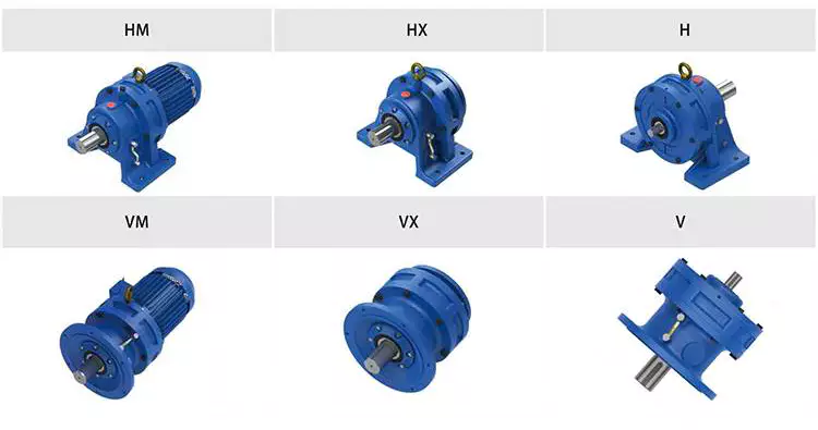
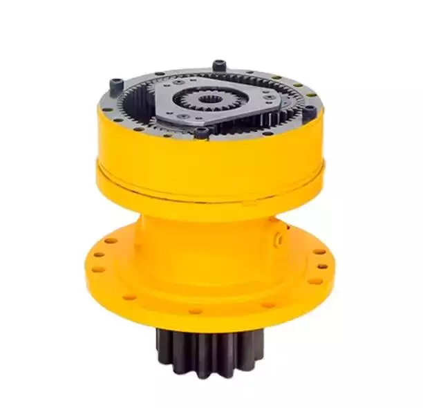
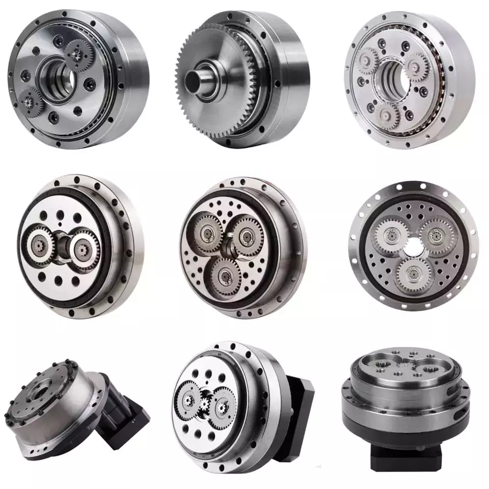
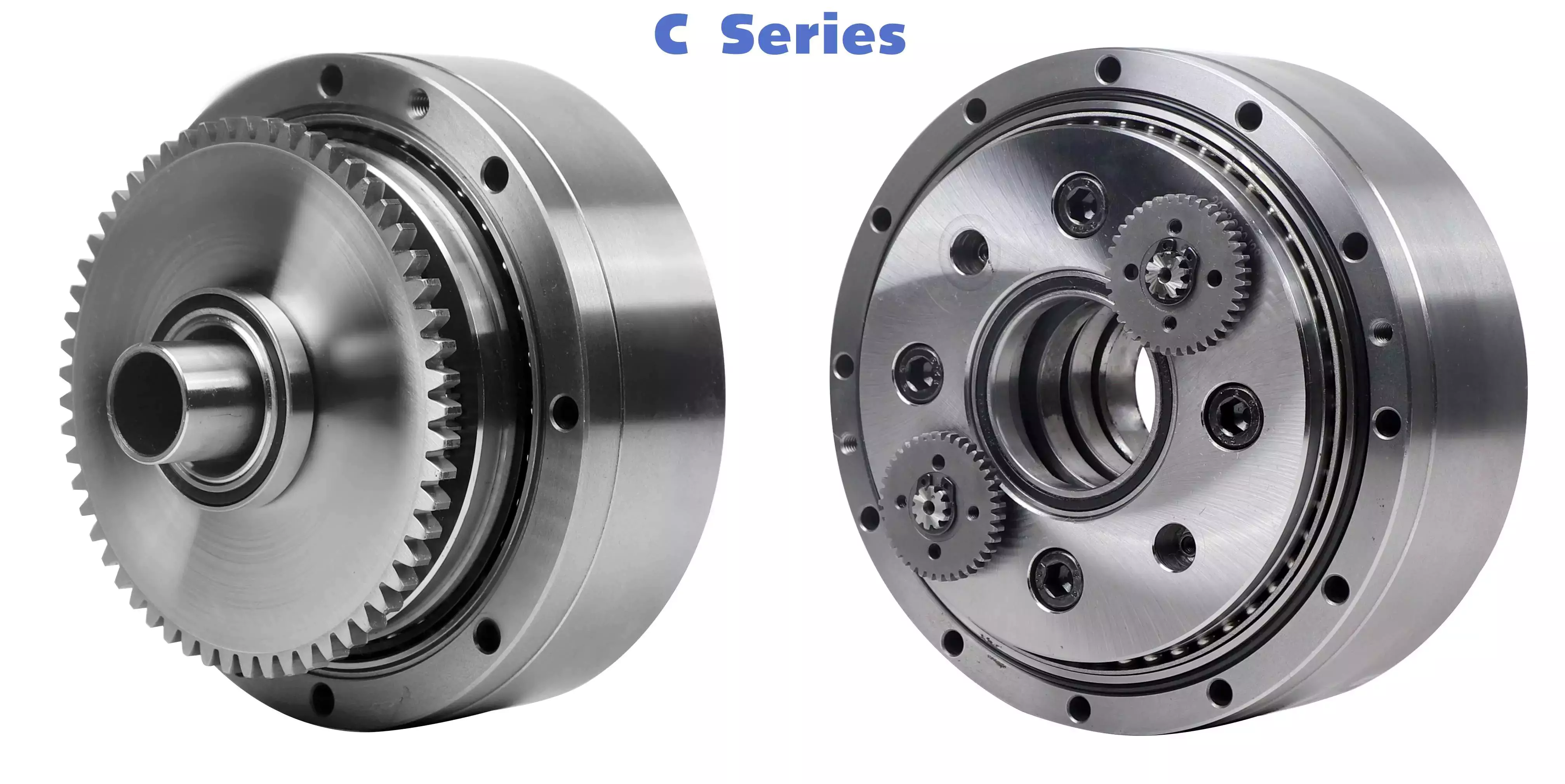
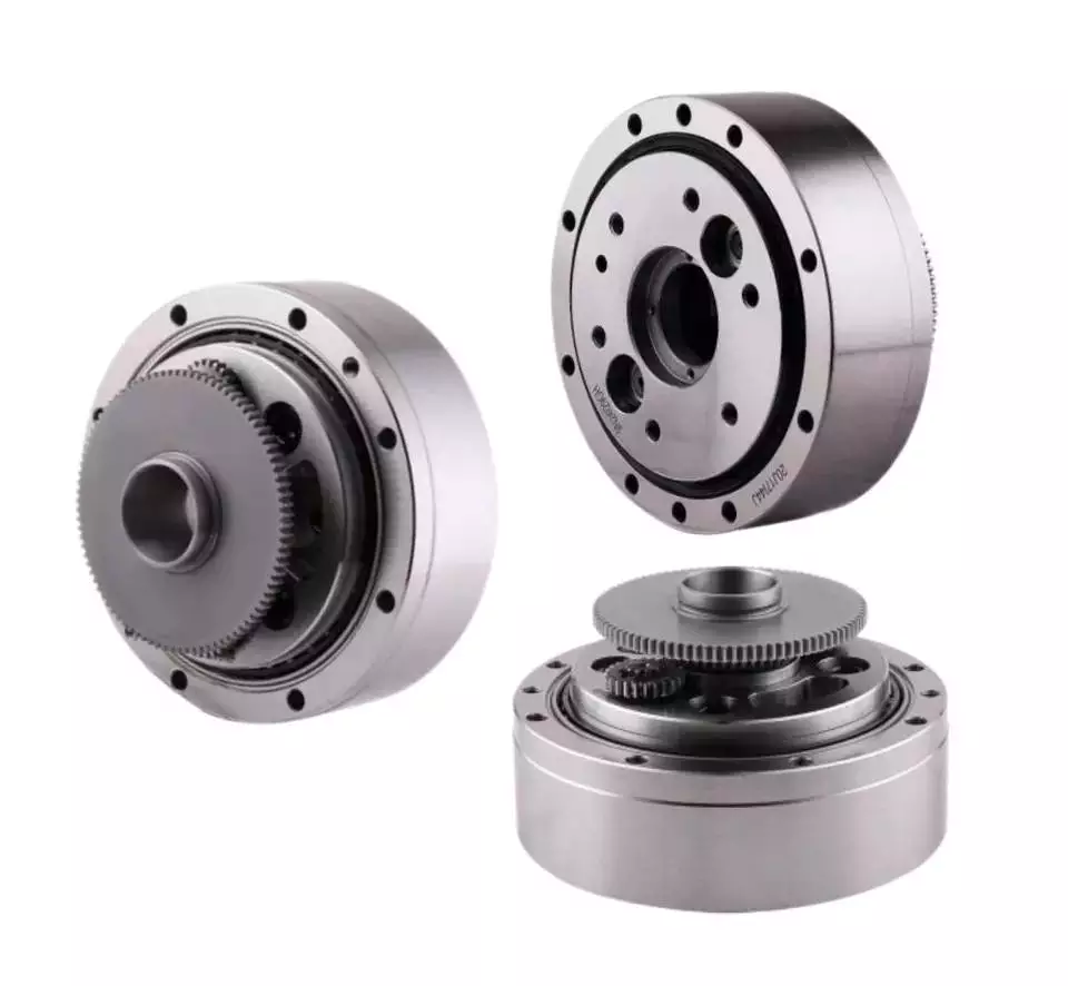
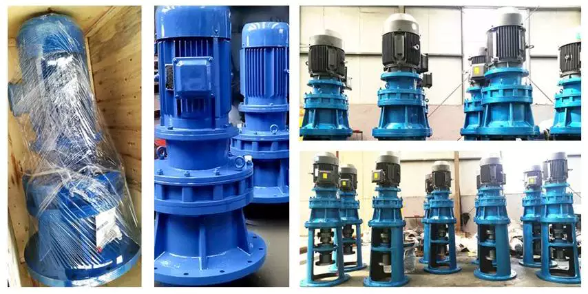
China Cycloidal Pinwheel Transmission Reduce Box Gear Gearbox Speed Reducer Cast Iron Ratio 29 China ZHEJIANG, China 0.3-167RPM with Great quality

Guarantee: 1 12 months, twelve Months
Applicable Industries: Constructing Content Stores, Producing Plant, Food & Beverage Manufacturing unit, Farms, Design works , Vitality & Mining, Foods & Beverage Shops
Custom-made assistance: OEM, ODM
Gearing Arrangement: Cycloidal
Output Torque: UP TO 2000NM
Input Pace: 1500RPM
Output Velocity: .3-167RPM
Coloration: Blue(RAL5571)/Silver/ Gray
Mounting Place: vertical/ horizontal
Kind: X Series/ WB Sequence
Packaging Specifics: Common export Plywood circumstance
Port: HangZhou & ZheJiang

Merchandise Description Attributes1:Leading in-line drives as both a reducer and gearmotor2:Quiet, efficient and dependable procedure with high torque density and compact sizes3:Interchangeable forged iron housings in foot, Factory value aluminum Locking shaft collar excellent high quality shaft collar flanged or encounter mount configurations4:Accessible free-shaft, quill hollow shaft, C-encounter adaptors, shovel foundation, and top-mount inputsfive:Mininimal vibration, lower sound, lower backlash and extended operational life6:The very best solution warranty with 24 months backs up the superb Cyclo solution reputation Firm Profile Workshop & Proessing method Certifications Why Us Strictly High quality Control provide Outstand Gearbox goods 1: 100% screening for all the gears and Gear shaft and forged Iron Housing 2: one hundred% Working Check ahead of shipping and delivery (Include Oil leak ,Noise and Vibration checkthree: one hundred% Appearance checking just before packing Robust Generation Capacity & Superior tools & CNC machining valve areas taper lock carbon metal with Dacromet SDS bushings More quickly deliveryone: Much more than 150 expert personnel & 40000 Squre meter manufacturing unit foundation2: Imported Grinding machines(REISHAUER) ,make certain all gears we make are DIN 6.three: Quick delivery (Spare component inventory for all sequence gearboxes)4: 29 years experience since 1993 five: Personalized gearbox according to client’s requrement Exhibition Application FAQ 1. How to choose a gearbox which meets our need?You can refer to our catalogue to select the gearbox or we can help to choose when you providethe specialized info of required output torque, output speed and motor parameter and so on.2. What info shall we give prior to positioning a acquire get?a) Variety of the gearbox, ratio, enter and output variety, input flange, mounting place, and motor info , Aluminum Alloy Shaft Correcting Bracket Pillar Repairing Clamp with Threaded Parallel Xihu (West Lake) Dis. Shaft Assist Pipe Clamp Bearing Housing and many others.b) Housing color.c) Buy quantity.d) Other unique needs.3. What industries are your gearboxes being utilized?Our gearboxes are commonly utilised in the regions of textile, foods processing, beverage, chemical sector,escalator,automatic storage tools, metallurgy, tabacco, environmental safety, logistics and and so forth.4. Do you offer motors?We have steady motor suppliers who have been coperating with us for a lengthy-time. They can offer motorswith large quality.

The Different Types of Gearboxes

There are many different types of gearboxes. Some brands have more than one type. In this article, we’ll discuss the planetary gearbox, the worm reduction gearbox, the shaft mounted gearbox, and the one speed gearbox. This article will also help you determine which type of gearbox is best for your vehicle. And don’t worry if you don’t know the terminology yet. We’ll explain each type in detail so that you know what you’re getting yourself into.
gearbox

Planetary gearbox

Planetary gears have many advantages. The multiple gears in a planetary gearbox mesh simultaneously during operation. As such, they provide high efficiency and transmit high transmittable torque. These gears are widely used in various industries and are resistant to high shock loads and demanding conditions. CZPT is one of the companies that offer planetary gearboxes. Its products do not require special tools for assembly, and its scalable design minimizes safety stock.
Among the numerous benefits of planetary gearing is its compactness and lightweight. As such, it is suitable for wide applications with space and weight constraints. However, to truly appreciate its benefits, it is necessary to understand its mechanisms. Here are some of the most common details about planetary gearing:
The planetary gearbox has two mounted gears: an input shaft and an output shaft. Each gear has multiple teeth that are attached to a carrier and rotate with the input shaft. The carrier is connected to the output shaft. A planetary gear is mounted on both gears via a carrier. The carrier rotates in order to drive the planetary gear. The sun gear is often the input gear. The other gear is called the outer gear.
Planetary gearboxes are highly customizable. The size, mounting, and housing options vary, as do the reduction ratios and input speeds. Different types can be manufactured for different applications and include options such as electrical or mechanical preload. The final design of a planetary gearbox can be highly customized, based on the specifications of the application. By combining engineering excellence and ongoing innovation, planetary gearboxes provide years of trouble-free operation.
A planetary gearbox can be either an electric motor or a manual one. The latter has more features than the former, and can be used in applications where space is an issue. The primary features of a planetary gearbox include its backlash, torque, and ratio. Secondary features include noise, corrosion resistance, and construction. A planetary gearbox is a highly versatile gearbox that can drive anything from simple machinery to advanced electrical systems.
gearbox

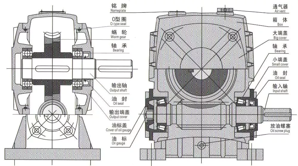
Worm reduction gearbox

The global worm reduction gearbox market report compiles key insights from the industry to help you improve your business strategy. This report will help you create a comprehensive business document that will enhance your company’s competitive edge. To obtain this report, visit our website now! Read our latest report to find out what you can expect from the global worm reduction gearbox market. Alternatively, request a sample copy for more details. Here is a sneak peek of the report:
Worm gears are made with different thread counts and are usually not matched with the CZPT standard. In general, a single thread worm should be used with a single thread worm. Worm gears have either right or left threads, and their thread count will be different as well. This type of gear is used to reduce the speed of a rotating shaft. The speed reduction ratio will be about 50 percent if the worms have the same thread count as the CZPT gears.
The standard gear set transfers power at the peak load point of a tooth, called the pitchline. The worm gear moves slowly against the wheel’s metal surface. The worm gear is also more complex than the standard gear because the worm is sliding rather than rolling. Worm gears are hard to lubricate. Moreover, the sliding contact between the gear and worm increases the complexity of the gear set. They can be a great solution for applications where noise is a significant factor.
The axial pitch and circular pitch of the worm are equal. The ratio of these two indices determines the speed of transmission. For a worm reduction gearbox to work, the axial pitch and the circular pitch must match. The pitch angle of a worm can either be left-handed or right-handed. The lead of a worm is the distance one thread travels in one revolution. The lead angle is the angle tangent to the thread helix of the cylinder’s pitch. When a worm mesh is reversed, the majority of the mesh will be on the receding arc.
Worm gears generate more heat than their counterparts, so it is important to choose a worm reduction gearbox carefully. You will want to choose the material and amount of lubricating oil carefully. Worm gears are generally made of tin bronze. The paired worms are hardened to HRC45-55. In general, they are durable, lasting up to ten years. But they will wear out – and they wear out – so you may want to consider some other factors.

Shaft-mounted gearbox

Shaft-mounted gearboxes are designed for a variety of mining and quarry applications. Their high reliability and low maintenance make them an excellent choice in these types of applications. Shaft-mounted gearboxes also feature an optional backstop device that prevents the unit from rotating in one direction. This makes them an excellent choice for applications where alignment accuracy is an issue. Here are some of the benefits of using a shaft-mounted gearbox:
Shaft-mounted gearboxes are typically constructed of aluminium, and come in sizes ranging from 050 to 125. They feature a variety of reduction ratios and ensure optimum efficiency in all operating conditions. New S series sizes, 140 and 150, extend the application range of shaft-mounted gearmotors. They are both backed by a two-year warranty. For even greater peace of mind, Shaft-mounted gearboxes are available with a range of warranty options.
The most common applications for a Shaft-mounted gearbox include traction-driven applications where a low-speed shaft is required for operation. They also are suitable for applications without a foundation, where the motor is mounted next to the reducer. To prevent the gear drive from rotating, a torque arm is attached between the motor and the shaft. Small-sized shaft-mounted gear drives are usually made without motor mount kits, which can make them an excellent choice for conveying light loads.
Another important feature of a Shaft-mounted gearbox is its mounting position. The reduced motion through the drive is redirected through the shaft, creating additional forces. These additional forces can affect the performance of the gearbox, causing vibrations and noise. Consequently, it is important to replace worn or damaged belts on a regular basis. Further, shaft-mounted gearboxes can be affected by problems with other components and amplify vibrations.
gearbox

1 speed gearbox

CZPT Group Components produces one speed gearboxes. These transmissions are produced in the CZPT Group’s Kassel plant. They are compact and robust, and are designed for easy integration. The Bosch Rexroth GD1 one-speed gearbox is easy to install horizontally or vertically. The Plug and Drive system integrates the gearbox with the existing cooling system. There are many other benefits to this gearbox.
With an ID.3 electric drive motor, the maximum torque is delivered at 16,000 rpm. This single-speed transmission offers high power density and excellent noise-reduction, making it ideal for electric vehicles. The e-drive motor is extremely quiet and requires precision manufacturing. The e-drive motor also enables a wide range of driving conditions. It can reverse when needed, and reaches its maximum speed at 16,000.
The single-speed gearbox is a standard feature on most electric vehicles. Some electric vehicles, such as the Porsche Taycan, will be equipped with a two-speed gearbox. This gearbox offers more top speed and range, but it is more complex than a standard single-speed gearbox. CZPT doesn’t need to add complexity to its electric vehicles. After all, a 355 horsepower family wagon is not likely to need a dual-speed gearbox.
In addition to simplifying the transmission, the patent claims also address improvements in structural design. Fig. 5 shows a schematic representation of a transmission 50′, wherein gear sets Z1 and Z4 are exchanged between partial transmissions. This switch matrix also reflects the synchronized gears and lastshelf gears. Hydraulically betatigte Lamellenkupplungen (HBA) also form a last-shelf gear.
Another advantage of the patent claim is that it offers numerous functional freedoms, which is especially valuable in the design of an automobile. One of the patent claims identifies a tosatzlicher middle gear that allows a driver to switch between second and third gears, with a single gearbox. In a conventional one-speed transmission, the tosatzlicher middle gear is attached to the second and first part gearbox. The latter has a second and third gear.

China Cycloidal Pinwheel Transmission Reduce Box Gear Gearbox Speed Reducer Cast Iron Ratio 29 China ZHEJIANG, China 0.3-167RPM     with Great quality China Cycloidal Pinwheel Transmission Reduce Box Gear Gearbox Speed Reducer Cast Iron Ratio 29 China ZHEJIANG, China 0.3-167RPM     with Great quality
editor by czh 2023-02-16

China Convenient Use Gearbox with Auxiliary Transmission and Transfer cycloidal gearbox efficiency

Item Description

Merchandise Description

Convenient Use Gearbox With Auxiliary Transmission And Transfer


Organization Profile


Our Benefits


Exhibition


Packaging & Delivery

FAQ

US $200-3,000
/ Piece
|
1 Piece

(Min. Order)

###

Application: Motor, Electric Cars, Motorcycle, Machinery, Marine, Car
Function: Distribution Power, Change Drive Torque, Change Drive Direction, Speed Changing, Speed Reduction, Speed Increase
Layout: Cycloidal
Hardness: Hardened Tooth Surface
Installation: Torque Arm Type
Step: Four-Step

###

Samples:
US$ 200/Piece
1 Piece(Min.Order)

|
Request Sample

###

Customization:

How to Use a Cyclone Gearbox

Often, a cycloidal gearbox is used in order to achieve a torque transfer from a motor or pump. This type of gearbox is often a common choice as it has a number of advantages over a regular gearbox. Its main advantage is that it is easy to make, which means that it can be incorporated into a variety of applications. However, if you want to use a cycloidal gearbox, there are a few things that you need to know. These include the operation principle, the structure and the dynamic and inertial effects that come with it.helical gearbox

Dynamic and inertial effects

Several studies have been carried out on the static and dynamic properties of cycloidal gears. The study of these effects is beneficial in assisting optimal design of cycloidal speed reducers.
In this paper, the dynamic and inertial effects of a two-stage cycloidal speed reducer have been investigated using the CZPT program package. Moreover, a new model for cycloidal reducers based on non-linear contact dynamics has been developed. The new model aims to predict several operational conditions.
The normal excitation contact force for the cycloid discs of the first and second stage is very similar. However, the total deformation at the contact point is different. This effect is mainly due to the system’s own oscillations. The cycloid discs of the second stage turn around the ring gear roller with a 180deg angle. This angle is a significant contributor to the torque loads. The total excitation force on the cycloid discs of first and second stage is 1848 N and 2068.7 N, respectively.
In order to analyze the contact stress, different gear profiles were investigated. The mesh density was considered as an important design criterion. It was found that a bigger hole reduces the material content of the cycloidal disc and results in more stresses.
Moreover, it is possible to reduce the contact forces in a more efficient manner by changing the geometric parameters. This can be done by mesh refinement along the disc width. The cycloidal disc has the greatest influence on the output results.
The efficiency of a cycloidal drive increases with the increase in load. The efficiency of a cycloidal reducer also depends on the eccentricity of the input shaft and the cycloidal plate. The efficiency curve for small loads is linear. However, for the larger loads, the efficiency curve becomes more non-linear. This is because the stiffness of the cycloid reducer increases as the load increases.

Structure

Despite the fact that it looks like a complicated engineering puzzle, the construction of a cycloidal gearbox is actually quite simple. The key elements are the base, the load plate and the thrust bearing. All these elements work together to create a stable, compact gearbox.
The base is a circular section with several cylindrical pins around its outer edge. The pins are fixed on a fixed ring that holds them in a circular path. The ring serves as a reference circle. The circle’s size is approximately 5mm in diameter.
The load plate is a series of threaded screw holes. These are arranged 15mm away from the center. These are used to anchor external structures. The load plate must be rotated around the X and Y axis.
The thrust bearing is placed on top of the load plate. The bearing is made of an internal diameter of 35mm and an external diameter of 52mm. It is used to allow rotation around the Z axis.
The cycloidal disc is the centerpiece of the cycloidal gearbox. The disc has holes for the pins that drive the output shaft. The holes are larger than those used in output roller pins. The disc also has a reduced eccentricity.
The pins are attached to the cycloidal disc by rolling pins. The pins are made of a material that provides mechanical support for the drive during high-torque situations. The pins have a 9mm external diameter. The disc has a number of lobes and is rotated by one lobe per shaft revolution.
The cycloidal gearbox also has a top cover that helps keep the components together. The cover has a pocket for tools. The top cover also has threads that screw into the casing.helical gearbox

Operation principle

Among many types of gear transmissions, cycloidal gearboxes are used in heavy machinery and multi-axis robots. They are highly effective, compact and capable of high ratios. In addition, they have an overload capability.
Cycloid disks are driven by eccentric shafts that rotate around fixed ring pins. Roller pins of the pin disc engage with holes in the cycloidal disc. These roller pins drive the pin disc and the pin disc transfers the motion to the output shaft.
Unlike conventional gear drives, cycloidal drives have low backlash and high torsional stiffness. They are ideally suited to heavy loads and all drive technologies. The lower mass and compact design of the cycloidal disk also contributes to its high efficiency and positioning accuracy.
The cycloidal disc plays a central role in the gearbox kinematics. It rotates around a fixed ring in a circle. When the disc is pushed against the ring gear, the pins engage with the disc and the roller pins rotate around the pins. This rotating motion generates vibration, which travels through the driven shafts.
Cycloid discs are typically designed with a short cycloid, so that the eccentricity is minimized. This reduces unbalance forces at high speeds. Ideally, the number of lobes on the cycloid is smaller than the number of surrounding pins. This reduces the amount of Hertzian contact stress.
Unlike planetary gears, cycloidal gears have high accuracy and are capable of withstanding shock loads. They also experience low friction and less wear on tooth flanks. They also have higher efficiency and load capacity.
Cycloid gears are generally more difficult to manufacture than involute gears. Cycloid gears are not suitable for stacking gear stages. They require extreme accuracy for manufacturing. However, their smaller size and low backlash, high torsional stiffness, and low vibration make them ideal for use in heavy machines.

Involute gear tooth profile

Almost all gears are manufactured with an involute gear tooth profile. Cycloid gears are also produced with this profile. Compared with involute gears, cycloid gears are stronger and can transmit more power. However, they can also be more difficult to manufacture. This makes them costlier.
The involute gear tooth profile is a smooth curve. It is derived from the involute curve of a circle. A tangent to the base circle is the normal at any point of an involute.
This curve has properties that allow the involute gear teeth to transfer motion in perpendicular direction. It is also the path traced by the end of the string unwrapping from a cylinder.
An involute profile has the advantage of being easy to manufacture. It also allows for smooth meshing despite misalignment of the centre distance. This profile is also preferred over a cycloid tooth profile, but it is not the best in every regard.
Cycloid gear teeth are also made of two curves. Unlike involute teeth, cycloid gear teeth have a consistent radius. Cycloid gears are less likely to produce noise. But they are also more expensive to manufacture.
Involute teeth are easier to manufacture because they have only one curve. Cycloid gears can also be made with a rack type cutter. This makes them cheaper to manufacture. However, they require an expert design. They can also be manufactured with a gear shaper that includes a pinion cutter.
The tooth profiles that satisfy the law of gear-tooth action are sometimes called conjugate profiles. The involute profile is the most common of these. It allows for constant torque transmission.helical gearbox

Backlash

Typically, cycloidal drives provide a high ratio of transmission with no backlash. This is because the cycloid disc is driven by an eccentric shaft. During rotation, the cycloid disc rotates around a fixed ring. This ring also rotates independently of the center of gravity.
The cycloid disc is typically shortened to reduce the eccentricity. This helps to minimize the unbalance forces that may occur at high speeds. The cycloid also offers a larger gear ratio than traditional gears. This provides a better positional accuracy.
Cycloid drives also have a high torsional stiffness. This provides greater torsional resilience and shock load capabilities. This is important for a number of reasons, such as in heavy-duty applications.
Cycloid drives also have lower mass. These benefits make them ideally suited for all drive technologies. The design also allows for higher torsional stiffness and service life. These drives also have a much smaller profile.
Cycloid drives are also used to reduce speed. Because of the high torsional stiffness of the cycloid, they also have high positioning accuracy.
Cycloid drives are well-suited to a variety of applications, including electric motors, generators, and pump motors. They are also highly resistant to shock loads, which is important in a variety of applications. This design is ideal for applications that require a large transmission ratio in a compact design.
Cycloid drives also have the advantage of minimizing the clearance between the mating components. This helps to eliminate interference and ensure a positive fit. This is particularly important in gearboxes. It also allows for the use of a load cell and potentiometer to determine the backlash of the gearbox.
China Convenient Use Gearbox with Auxiliary Transmission and Transfer     cycloidal gearbox efficiencyChina Convenient Use Gearbox with Auxiliary Transmission and Transfer     cycloidal gearbox efficiency
editor by czh 2023-01-06

China Bx Cycloidal Drive Transmission Gear Reducer Speed Gearbox cycloidal drive mechanism

Item Description

XWD2/ XWD3/XWD4/XWD5/XWD6/XWD7 /XWD8 gearbox with ac motor 

Cycloidal reducer adopts meshing cycloid pin equipment, planetary transmission principle, so usually also referred to as planetary cycloid reducer.  Planetary cycloidal reducer can be widely employed in petroleum, environmental protection, chemical, cement, transportation, textile, pharmaceutical, food, printing, lifting, mining, metallurgy, construction, power technology and other industries.
      As a travel or reduction equipment,  the machine is divided into horizontal, vertical, biaxial and straight league assembly way,and so on.  Its distinctive secure construction can exchange normal cylindrical equipment reducer and worm equipment reducer in a lot of situations. As a result, planetary cycloid equipment reducer is widely used in a variety of industries and fields, and is normally welcomed by the bulk of customers.

XWD/BWY cycloid  reducer motor details:

B sequence:

BW basedoard horizontal put in double axes type 

BL flange vertical mounted double axes kind

BWY  basedoard horizontal put in motor direct-relationship variety

BLY   flange vertical put in motor immediate-link kind

X series:

XW basedoard horizontal set up double axes variety

XL flange vertical put in double axes variety

XWD basedoard horizontal installed motor direct-connection type

XLD flange vertical mounted motor direct-relationship type


FAQ
one, Q:what is your MOQ for ac gearbox motor  ?
A: 1pc is okay for every type electrical equipment box  motor 

2, Q: What about your guarantee for your induction pace reducer motor ?
A: 1 year ,but other than gentleman-manufactured wrecked

three, Q: which payment way you can take ?
A: TT, western union .

4, Q: how about your payment way ?
A: a hundred%payment in advanced considerably less $5000 ,30% payment in superior payment , 70% payment prior to sending more than $5000.

five, Q: how about your packing of speed reduction motor  ?
A: plywood case ,if dimensions is tiny  ,we will pack with pallet for much less 1 container 

6, Q: What data must be given, if I get electric powered helical geared motor  from you ?
A: rated electrical power,  ratio or output velocity,variety ,voltage , mounting way , amount , if much more is greater , 
 

US $30-200
/ Piece
|
5 Pieces

(Min. Order)

###

Application: Motor, Machinery, Agricultural Machinery
Function: Speed Changing, Speed Reduction
Layout: Cycloidal
Hardness: Hardened Tooth Surface
Installation: Horizontal Type
Step: Single-Step

###

Customization:
US $30-200
/ Piece
|
5 Pieces

(Min. Order)

###

Application: Motor, Machinery, Agricultural Machinery
Function: Speed Changing, Speed Reduction
Layout: Cycloidal
Hardness: Hardened Tooth Surface
Installation: Horizontal Type
Step: Single-Step

###

Customization:

The Cyclonoidal Gearbox

Basically, the cycloidal gearbox is a gearbox that uses a cycloidal motion to perform its rotational movement. It is a very simple and efficient design that can be used in a variety of applications. A cycloidal gearbox is often used in applications that require the movement of heavy loads. It has several advantages over the planetary gearbox, including its ability to be able to handle higher loads and higher speeds.helical gearbox

Dynamic and inertial effects of a cycloidal gearbox

Several studies have been conducted on the dynamic and inertial effects of a cycloidal gearbox. Some of them focus on operating principles, while others focus on the mathematical model of the gearbox. This paper examines the mathematical model of a cycloidal gearbox, and compares its performance with the real-world measurements. It is important to have a proper mathematical model to design and control a cycloidal gearbox. A cycloidal gearbox is a two-stage gearbox with a cycloid disc and a ring gear that revolves around its own axis.
The mathematical model is made up of more than 1.6 million elements. Each gear pair is represented by a reduced model with 500 eigenmodes. The eigenfrequency for the spur gear is 70 kHz. The modally reduced model is a good fit for the cycloidal gearbox.
The mathematical model is validated using ABAQUS software. A cycloid disc was discretized to produce a very fine model. It requires 400 element points per tooth. It was also verified using static FEA. This model was then used to model the stiction of the gears in all quadrants. This is a new approach to modelling stiction in a cycloidal gearbox. It has been shown to produce results comparable to those of the EMBS model. The results are also matched by the elastic multibody simulation model. This is a good fit for the contact forces and magnitude of the cycloid gear disc. It was also found that the transmission accuracy between the cycloid gear disc and the ring gear is about 98.5%. However, this value is lower than the transmission accuracy of the ring gear pair. The transmission error of the corrected model is about 0.3%. The transmission accuracy is less because of the lower amount of elastic deformation on the tooth flanks.
It is important to note that the most accurate contact forces for each tooth of a cycloid gearbox are not smooth. The contact force on a single tooth starts with a linear rise and then ends with a sharp drop. It is not as smooth as the contact force on a point contact, which is why it has been compared to the contact force on an ellipse contact. However, the contact on an ellipse contact is still relatively small, and the EMBS model is not able to capture this.
The FE model for the cycloid disc is about 1.6 million elements. The most important part of the FE model is the discretization of the cycloid disc. It is very important to do the discretization of the cycloid gear disc very carefully because of the high degree of vibration that it experiences. The cycloid disc has to be discretized finely so that the results are comparable to those of a static FEA. It has to be the most accurate model possible in order to be able to accurately simulate the contact forces between the cycloid disc and the ring gear.helical gearbox

Kinematics of a cycloidal drive

Using an arbitrary coordinate system, we can observe the motion of components in a cycloidal gearbox. We observe that the cycloidal disc rotates around fixed pins in a circle, while the follower shaft rotates around the eccentric cam. In addition, we see that the input shaft is mounted eccentrically to the rolling-element bearing.
We also observe that the cycloidal disc rotates independently around the eccentric bearing, while the follower shaft rotates around an axis of symmetry. We can conclude that the cycloidal disc plays a pivotal role in the kinematics of a cycloidal gearbox.
To calculate the efficiency of the cycloidal reducer, we use a model that is based on the non-linear stiffness of the contacts. In this model, the non-linearity of the contact is governed by the non-linearity of the force and the deformation in the contact. We have shown that the efficiency of the cycloidal reducer increases as the load increases. In addition, the efficiency is dependent on the sliding velocity and the deformations of the normal load. These factors are considered as the key variables to determine the efficiency of the cycloidal drive.
We also consider the efficiency of the cycloidal reducer with the input torque and the input speed. We can calculate the efficiency by dividing the net torque in the ring gear by the output torque. The efficiency can be adjusted to suit different operating conditions. The efficiency of the cycloidal drive is increased as the load increases.
The cycloidal gearbox is a multi-stage gearbox with a small shaft oin and a big shaft. It has 19 teeth and brass washers. The outer discs move in opposition to the middle disc, and are offset by 180 deg. The middle disc is twice as massive as the outer disc. The cycloidal disc has nine lobes that move by one lobe per drive shaft revolution. The number of pins in the disc should be smaller than the number of pins in the surrounding pins.
The input shaft drives an eccentric bearing that is able to transmit the power to the output shaft. In addition, the input shaft applies forces to the cycloidal disk through the intermediate bearing. The cycloidal disk then advances in 360 deg/pivot/roller steps. The output shaft pins then move around in the holes to make the output shaft rotate continuously. The input shaft applies a sinusoidal motion to maintain the constant speed of the base shaft. This sine wave causes small adjustments to the follower shaft. The forces applied to the internal sleeves are a part of the equilibrium mechanism.
In addition, we can observe that the cycloidal drive is capable of transmitting a greater torque than the planetary gear. This is due to the cycloidal gear’s larger axial length and the ring gear’s smaller hole diameter. It is also possible to achieve a positive fit between the fixed ring and the disc, which is achieved by toothing between the fixed ring and the disc. The cycloidal disk is usually designed with a short cycloid to minimize unbalance forces at high speeds.helical gearbox

Comparison with planetary gearboxes

Compared to planetary gearboxes, the cycloidal gearbox has some advantages. These advantages include: low backlash, better overload capacity, a compact design, and the ability to perform in a wide range of applications. The cycloidal gearbox has become popular in the multi-axis robotics market. The gearbox is also increasingly used in first joints and positioners.
A cycloidal gearbox is a gearbox that consists of four basic components: a cycloid disk, an output flange, a ring gear, and a fixed ring. The cycloid disk is driven by an eccentric shaft, which advances in a 360deg/pivot/roller step. The output flange is a fixed pin disc that transmits the power to the output shaft. The ring gear is a fixed ring, and the input shaft is connected to a servomotor.
The cycloidal gearbox is designed to control inertia in highly dynamic situations. These gearboxes are generally used in robotics and positioners, where they are used to position heavy loads. They are also commonly used in a wide range of industrial applications. They have higher torque density and a low backlash, making them ideal for heavy loads.
The output flange is also designed to handle a torque of up to 500 Nm. Its rotational speed is lower than the planet gearbox, but its output torque is much higher. It is designed to be a high-performance gearbox, and it can be used in applications that need high ratios and a high level of torque density. The cycloid gearbox is also less expensive and has less backlash. However, the cycloidal gearbox has disadvantages that should be considered when designing a gearbox. The main problem is vibrations.
Compared to planetary gearboxes, cycloidal gearboxes have a smaller overall size and are less expensive. In addition, the cycloid gearbox has a large reduction ratio in one stage. In general, cycloidal gearboxes have single or two stages, with the third stage being less common. However, the cycloid gearbox is not the only type of gearbox that has this type of configuration. It is also common to find a planetary gearbox with a single stage.
There are several different types of cycloidal gearboxes, and they are often referred to as cycloidal speed reducers. These gearboxes are designed for any industry that uses servos. They are shorter than planetary gearboxes, and they are larger in diameter for the same torque. Some of them are also available with a ratio lower than 30:1.
The cycloid gearbox can be a good choice for applications where there are high rotational speeds and high torque requirements. These gearboxes are also more compact than planetary gearboxes, and are suitable for high-torque applications. In addition, they are more robust and can handle shock loads. They also have low backlash, and a higher level of accuracy and positioning accuracy. They are also used in a wide range of applications, including industrial robotics.
China Bx Cycloidal Drive Transmission Gear Reducer Speed Gearbox     cycloidal drive mechanismChina Bx Cycloidal Drive Transmission Gear Reducer Speed Gearbox     cycloidal drive mechanism
editor by czh 2023-01-03

China Energy Saving Skm Series Helical Hypoid Gear Speed Reducer Transmission Gearbox cycloidal drive purpose

Merchandise Description

1. Specialized functions

The large diploma of modularity is a layout characteristic of SKM, SKB sequence helical-hypoid gear units. It can be connected respectively with motors this sort of as typical mtor, brake motor, explosion -evidence motor, frequency conversion motor, servo motor, IEC motor and so on. This kind of merchandise is commonly utilized in drive fields this kind of as textile, foodstuff, ceramice packing, logistics, plastics and so on.

1.1 Item attributes

SKM SKB Seires helical gear models has far more than 4 varieties. Power .12-4kw, Ratio 7.seventy three-302.5, Torque max100-500 NM, Modulaw and multistructure can meet the demands of different situations.

(1)Floor-hardened helical gears.
(2)Modularity, can be mixed in several kinds.
(3)Manufactured of large-top quality aluminum alloy, light in excess weight and nonrusting.
(4)Huge in output torque, higher effectiveness, ene-rgy preserving and environmental safety.
(5)The mounting dimension of SKM collection are compatible with SMRV collection worm gear device(A part of SMRV050 proportions are diverse from SKM28)
(6)The mounting dimension of SKB collection are suitable with W series worm gear unit.

US $100
/ Piece
|
1 Piece

(Min. Order)

###

Shipping Cost:

Estimated freight per unit.


To be negotiated|


Freight Cost Calculator

###

Function: Speed Reduction
Layout: Cycloidal
Hardness: Hardened Tooth Surface

###

Customization:
US $100
/ Piece
|
1 Piece

(Min. Order)

###

Shipping Cost:

Estimated freight per unit.


To be negotiated|


Freight Cost Calculator

###

Function: Speed Reduction
Layout: Cycloidal
Hardness: Hardened Tooth Surface

###

Customization:

The Cyclonoidal Gearbox

Basically, the cycloidal gearbox is a gearbox that uses a cycloidal motion to perform its rotational movement. It is a very simple and efficient design that can be used in a variety of applications. A cycloidal gearbox is often used in applications that require the movement of heavy loads. It has several advantages over the planetary gearbox, including its ability to be able to handle higher loads and higher speeds.helical gearbox

Dynamic and inertial effects of a cycloidal gearbox

Several studies have been conducted on the dynamic and inertial effects of a cycloidal gearbox. Some of them focus on operating principles, while others focus on the mathematical model of the gearbox. This paper examines the mathematical model of a cycloidal gearbox, and compares its performance with the real-world measurements. It is important to have a proper mathematical model to design and control a cycloidal gearbox. A cycloidal gearbox is a two-stage gearbox with a cycloid disc and a ring gear that revolves around its own axis.
The mathematical model is made up of more than 1.6 million elements. Each gear pair is represented by a reduced model with 500 eigenmodes. The eigenfrequency for the spur gear is 70 kHz. The modally reduced model is a good fit for the cycloidal gearbox.
The mathematical model is validated using ABAQUS software. A cycloid disc was discretized to produce a very fine model. It requires 400 element points per tooth. It was also verified using static FEA. This model was then used to model the stiction of the gears in all quadrants. This is a new approach to modelling stiction in a cycloidal gearbox. It has been shown to produce results comparable to those of the EMBS model. The results are also matched by the elastic multibody simulation model. This is a good fit for the contact forces and magnitude of the cycloid gear disc. It was also found that the transmission accuracy between the cycloid gear disc and the ring gear is about 98.5%. However, this value is lower than the transmission accuracy of the ring gear pair. The transmission error of the corrected model is about 0.3%. The transmission accuracy is less because of the lower amount of elastic deformation on the tooth flanks.
It is important to note that the most accurate contact forces for each tooth of a cycloid gearbox are not smooth. The contact force on a single tooth starts with a linear rise and then ends with a sharp drop. It is not as smooth as the contact force on a point contact, which is why it has been compared to the contact force on an ellipse contact. However, the contact on an ellipse contact is still relatively small, and the EMBS model is not able to capture this.
The FE model for the cycloid disc is about 1.6 million elements. The most important part of the FE model is the discretization of the cycloid disc. It is very important to do the discretization of the cycloid gear disc very carefully because of the high degree of vibration that it experiences. The cycloid disc has to be discretized finely so that the results are comparable to those of a static FEA. It has to be the most accurate model possible in order to be able to accurately simulate the contact forces between the cycloid disc and the ring gear.helical gearbox

Kinematics of a cycloidal drive

Using an arbitrary coordinate system, we can observe the motion of components in a cycloidal gearbox. We observe that the cycloidal disc rotates around fixed pins in a circle, while the follower shaft rotates around the eccentric cam. In addition, we see that the input shaft is mounted eccentrically to the rolling-element bearing.
We also observe that the cycloidal disc rotates independently around the eccentric bearing, while the follower shaft rotates around an axis of symmetry. We can conclude that the cycloidal disc plays a pivotal role in the kinematics of a cycloidal gearbox.
To calculate the efficiency of the cycloidal reducer, we use a model that is based on the non-linear stiffness of the contacts. In this model, the non-linearity of the contact is governed by the non-linearity of the force and the deformation in the contact. We have shown that the efficiency of the cycloidal reducer increases as the load increases. In addition, the efficiency is dependent on the sliding velocity and the deformations of the normal load. These factors are considered as the key variables to determine the efficiency of the cycloidal drive.
We also consider the efficiency of the cycloidal reducer with the input torque and the input speed. We can calculate the efficiency by dividing the net torque in the ring gear by the output torque. The efficiency can be adjusted to suit different operating conditions. The efficiency of the cycloidal drive is increased as the load increases.
The cycloidal gearbox is a multi-stage gearbox with a small shaft oin and a big shaft. It has 19 teeth and brass washers. The outer discs move in opposition to the middle disc, and are offset by 180 deg. The middle disc is twice as massive as the outer disc. The cycloidal disc has nine lobes that move by one lobe per drive shaft revolution. The number of pins in the disc should be smaller than the number of pins in the surrounding pins.
The input shaft drives an eccentric bearing that is able to transmit the power to the output shaft. In addition, the input shaft applies forces to the cycloidal disk through the intermediate bearing. The cycloidal disk then advances in 360 deg/pivot/roller steps. The output shaft pins then move around in the holes to make the output shaft rotate continuously. The input shaft applies a sinusoidal motion to maintain the constant speed of the base shaft. This sine wave causes small adjustments to the follower shaft. The forces applied to the internal sleeves are a part of the equilibrium mechanism.
In addition, we can observe that the cycloidal drive is capable of transmitting a greater torque than the planetary gear. This is due to the cycloidal gear’s larger axial length and the ring gear’s smaller hole diameter. It is also possible to achieve a positive fit between the fixed ring and the disc, which is achieved by toothing between the fixed ring and the disc. The cycloidal disk is usually designed with a short cycloid to minimize unbalance forces at high speeds.helical gearbox

Comparison with planetary gearboxes

Compared to planetary gearboxes, the cycloidal gearbox has some advantages. These advantages include: low backlash, better overload capacity, a compact design, and the ability to perform in a wide range of applications. The cycloidal gearbox has become popular in the multi-axis robotics market. The gearbox is also increasingly used in first joints and positioners.
A cycloidal gearbox is a gearbox that consists of four basic components: a cycloid disk, an output flange, a ring gear, and a fixed ring. The cycloid disk is driven by an eccentric shaft, which advances in a 360deg/pivot/roller step. The output flange is a fixed pin disc that transmits the power to the output shaft. The ring gear is a fixed ring, and the input shaft is connected to a servomotor.
The cycloidal gearbox is designed to control inertia in highly dynamic situations. These gearboxes are generally used in robotics and positioners, where they are used to position heavy loads. They are also commonly used in a wide range of industrial applications. They have higher torque density and a low backlash, making them ideal for heavy loads.
The output flange is also designed to handle a torque of up to 500 Nm. Its rotational speed is lower than the planet gearbox, but its output torque is much higher. It is designed to be a high-performance gearbox, and it can be used in applications that need high ratios and a high level of torque density. The cycloid gearbox is also less expensive and has less backlash. However, the cycloidal gearbox has disadvantages that should be considered when designing a gearbox. The main problem is vibrations.
Compared to planetary gearboxes, cycloidal gearboxes have a smaller overall size and are less expensive. In addition, the cycloid gearbox has a large reduction ratio in one stage. In general, cycloidal gearboxes have single or two stages, with the third stage being less common. However, the cycloid gearbox is not the only type of gearbox that has this type of configuration. It is also common to find a planetary gearbox with a single stage.
There are several different types of cycloidal gearboxes, and they are often referred to as cycloidal speed reducers. These gearboxes are designed for any industry that uses servos. They are shorter than planetary gearboxes, and they are larger in diameter for the same torque. Some of them are also available with a ratio lower than 30:1.
The cycloid gearbox can be a good choice for applications where there are high rotational speeds and high torque requirements. These gearboxes are also more compact than planetary gearboxes, and are suitable for high-torque applications. In addition, they are more robust and can handle shock loads. They also have low backlash, and a higher level of accuracy and positioning accuracy. They are also used in a wide range of applications, including industrial robotics.
China Energy Saving Skm Series Helical Hypoid Gear Speed Reducer Transmission Gearbox     cycloidal drive purposeChina Energy Saving Skm Series Helical Hypoid Gear Speed Reducer Transmission Gearbox     cycloidal drive purpose
editor by czh 2022-12-29

China Gpb090 Planetary Gvb Gpg Gear Box Transmission Gearbox Gearhead with Good Price cycloidal gearboxes

Item Description

TaiBang Motor Industry Group Co., Ltd.

The main products is induction motor, reversible motor, DC brush equipment motor, DC brushless gear motor, CH/CV massive gear motors, Planetary equipment motor ,Worm gear motor etc, which utilized extensively in various fields of producing pipelining, transportation, meals, medication, printing, cloth, packing, office, equipment, leisure and many others, and is the chosen and matched product for automatic equipment. 

Design Instruction

GB090-10-P2

GB 090 571 P2
Reducer Collection Code Exterior Diameter Reduction Ratio Reducer Backlash
GB:Higher Precision Sq. Flange Output

GBR:Large Precision Proper Angle Sq. Flange Output

GE:High Precision Round Flange Output

GER:Substantial Precision Right Round Flange Output

050:ø50mm
070:ø70mm
090:ø90mm
one hundred twenty:ø120mm
a hundred and fifty five:ø155mm
205:ø205mm
235:ø235mm
042:42x42mm
060:60x60mm
090:90x90mm
115:115x115mm
142:142x142mm
a hundred and eighty:180x180mm
220:220x220mm
571 indicates 1:ten P0:Substantial Precision Backlash

P1:Precision Backlash

P2:Standard Backlash

Principal Technological Efficiency
 

Product Quantity of stage Reduction Ratio GB042 GB060 GB060A GB090 GB090A GB115 GB142 GB180 GB220
Rotary Inertia 1 3 .03 .16   .sixty one   three.25 nine.21 28.98 69.sixty one
4 .03 .fourteen   .forty eight   2.74 7.54 23.sixty seven 54.37
5 .03 .thirteen   .forty seven   two.71 seven.42 23.29 fifty three.27
six .03 .13   .45   two.65 7.twenty five 22.75 fifty one.seventy two
7 .03 .thirteen   .45   2.62 7.14 22.forty eight 50.97
eight .03 .13   .44   two.58 7.07 22.59 fifty.eighty four
9 .03 .thirteen   .44   2.fifty seven 7.04 22.fifty three 50.sixty three
ten .03 .thirteen   .forty four   two.57 7.03 22.fifty one fifty.fifty six
2 15 .03 .03 .13 .thirteen .47 .forty seven two.71 seven.forty two 23.29
twenty .03 .03 .13 .thirteen .forty seven .47 2.71 seven.42 23.29
twenty five .03 .03 .13 .thirteen .47 .forty seven 2.71 7.forty two 23.29
30 .03 .03 .thirteen .thirteen .47 .forty seven two.71 seven.forty two 23.29
35 .03 .03 .thirteen .thirteen .forty seven .forty seven two.seventy one 7.forty two 23.29
forty .03 .03 .13 .13 .47 .47 two.seventy one seven.forty two 23.29
forty five .03 .03 .13 .thirteen .47 .forty seven 2.71 seven.forty two 23.29
50 .03 .03 .13 .thirteen .forty four .44 two.57 7.03 22.fifty one
sixty .03 .03 .13 .thirteen .forty four .44 two.57 7.03 22.fifty one
70 .03 .03 .thirteen .13 .forty four .44 2.fifty seven seven.03 22.51
eighty .03 .03 .thirteen .thirteen .44 .forty four two.57 7.03 22.fifty one
90 .03 .03 .thirteen .thirteen .44 .44 two.57 7.03 22.fifty one
a hundred .03 .03 .thirteen .thirteen .44 .forty four 2.fifty seven 7.03 22.fifty one


Item Variety of phase GB042 GB060 GB060A GB90 GB090A GB115 GB142 GB180 GB220
Backlash(arcmin) High Precision P0 one       ≤1 ≤1 ≤1 ≤1 ≤1 ≤1
2           ≤3 ≤3 ≤3 ≤3
Precision P1 1 ≤3 ≤3 ≤3 ≤3 ≤3 ≤3 ≤3 ≤3 ≤3
2 ≤5 ≤5 ≤5 ≤5 ≤5 ≤5 ≤5 ≤5 ≤5
Standard P2 one ≤5 ≤5 ≤5 ≤5 ≤5 ≤5 ≤5 ≤5 ≤5
two ≤7 ≤7 ≤7 ≤7 ≤7 ≤7 ≤7 ≤7 ≤7
Torsional Rigidity(N.M/arcmin) 1 three seven seven fourteen fourteen 25 fifty a hundred forty five 225
two three seven seven 14 14 25 50 145 225
Noise(dB) one,2 ≤56 ≤58 ≤58 ≤60 ≤60 ≤63 ≤65 ≤67 ≤70
Rated input velocity(rpm) 1,two 5000 5000 5000 4000 4000 4000 3000 3000 2000
Max enter pace(rpm) 1,2 ten thousand ten thousand ten thousand 8000 8000 8000 6000 6000 4000

 Noise take a look at common:Distance 1m,no load.Measured with an input speed 3000rpm 


US $50
/ Piece
|
1 Piece

(Min. Order)

###

Application: Machinery, Agricultural Machinery
Function: Distribution Power, Change Drive Torque, Change Drive Direction, Speed Reduction
Layout: Cycloidal
Hardness: Hardened Tooth Surface
Installation: Vertical Type
Step: Double-Step

###

Samples:
US$ 50/Piece
1 Piece(Min.Order)

|
Request Sample

###

Customization:

###

GB 090 010 P2
Reducer Series Code External Diameter Reduction Ratio Reducer Backlash
GB:High Precision Square Flange Output

GBR:High Precision Right Angle Square Flange Output

GE:High Precision Round Flange Output

GER:High Precision Right Round Flange Output

050:ø50mm
070:ø70mm
090:ø90mm
120:ø120mm
155:ø155mm
205:ø205mm
235:ø235mm
042:42x42mm
060:60x60mm
090:90x90mm
115:115x115mm
142:142x142mm
180:180x180mm
220:220x220mm
010 means 1:10 P0:High Precision Backlash

P1:Precision Backlash

P2:Standard Backlash

###

Item Number of stage Reduction Ratio GB042 GB060 GB060A GB090 GB090A GB115 GB142 GB180 GB220
Rotary Inertia 1 3 0.03 0.16   0.61   3.25 9.21 28.98 69.61
4 0.03 0.14   0.48   2.74 7.54 23.67 54.37
5 0.03 0.13   0.47   2.71 7.42 23.29 53.27
6 0.03 0.13   0.45   2.65 7.25 22.75 51.72
7 0.03 0.13   0.45   2.62 7.14 22.48 50.97
8 0.03 0.13   0.44   2.58 7.07 22.59 50.84
9 0.03 0.13   0.44   2.57 7.04 22.53 50.63
10 0.03 0.13   0.44   2.57 7.03 22.51 50.56
2 15 0.03 0.03 0.13 0.13 0.47 0.47 2.71 7.42 23.29
20 0.03 0.03 0.13 0.13 0.47 0.47 2.71 7.42 23.29
25 0.03 0.03 0.13 0.13 0.47 0.47 2.71 7.42 23.29
30 0.03 0.03 0.13 0.13 0.47 0.47 2.71 7.42 23.29
35 0.03 0.03 0.13 0.13 0.47 0.47 2.71 7.42 23.29
40 0.03 0.03 0.13 0.13 0.47 0.47 2.71 7.42 23.29
45 0.03 0.03 0.13 0.13 0.47 0.47 2.71 7.42 23.29
50 0.03 0.03 0.13 0.13 0.44 0.44 2.57 7.03 22.51
60 0.03 0.03 0.13 0.13 0.44 0.44 2.57 7.03 22.51
70 0.03 0.03 0.13 0.13 0.44 0.44 2.57 7.03 22.51
80 0.03 0.03 0.13 0.13 0.44 0.44 2.57 7.03 22.51
90 0.03 0.03 0.13 0.13 0.44 0.44 2.57 7.03 22.51
100 0.03 0.03 0.13 0.13 0.44 0.44 2.57 7.03 22.51

###

Item Number of stage GB042 GB060 GB060A GB90 GB090A GB115 GB142 GB180 GB220
Backlash(arcmin) High Precision P0 1       ≤1 ≤1 ≤1 ≤1 ≤1 ≤1
2           ≤3 ≤3 ≤3 ≤3
Precision P1 1 ≤3 ≤3 ≤3 ≤3 ≤3 ≤3 ≤3 ≤3 ≤3
2 ≤5 ≤5 ≤5 ≤5 ≤5 ≤5 ≤5 ≤5 ≤5
Standard P2 1 ≤5 ≤5 ≤5 ≤5 ≤5 ≤5 ≤5 ≤5 ≤5
2 ≤7 ≤7 ≤7 ≤7 ≤7 ≤7 ≤7 ≤7 ≤7
Torsional Rigidity(N.M/arcmin) 1 3 7 7 14 14 25 50 145 225
2 3 7 7 14 14 25 50 145 225
Noise(dB) 1,2 ≤56 ≤58 ≤58 ≤60 ≤60 ≤63 ≤65 ≤67 ≤70
Rated input speed(rpm) 1,2 5000 5000 5000 4000 4000 4000 3000 3000 2000
Max input speed(rpm) 1,2 10000 10000 10000 8000 8000 8000 6000 6000 4000

Developing a Mathematical Model of a Cyclone Gearbox

Compared to planetary gearboxes, cycloidal gearboxes are often seen as the ideal choice for a wide range of applications. They feature compact designs that are often low friction and high reduction ratios.helical gearbox

Low friction

Developing a mathematical model of a cycloidal gearbox was a challenge. The model was able to show the effects of a variety of geometric parameters on contact stresses. It was able to model stiction in all quadrants. It was able to show a clear correlation between the results from simulation and real-world measurements.
The model is based on a new approach that enables modeling stiction in all quadrants of a gearbox. It is also able to display non-zero current at standstill. Combined with a good simulation algorithm, the model can be used to improve the dynamic behaviour of a controlled system.
A cycloidal gearbox is a compact actuator used for industrial automation. This type of gearbox provides high gear ratios, low wear, and good torsional stiffness. In addition, it has good shock load capacity.
The model is based on cycloidal discs that engage with pins on a stationary ring gear. The resulting friction function occurs when the rotor begins to rotate. It also occurs when the rotor reverses its rotation. The model has two curves, one for motor and one for generator mode.
The trochoidal profile on the cycloidal disc’s periphery is required for proper mating of the rotating parts. In addition, the profile should be defined accurately. This will allow an even distribution of contact forces.
The model was used to compare the relative performance of a cycloidal gearbox with that of an involute gearbox. This comparison indicates that the cycloidal gearbox can withstand more load than an involute gearbox. It is also able to last longer. It is also able to produce high gear ratios in a small space.
The model used is able to capture the exact geometry of the parts. It can also allow a better analysis of stresses.

Compact

Unlike helical gearing, compact cycloidal gearboxes can provide higher reduction ratios. They are more compact and less weighty. In addition, they provide better positioning accuracy.
Cycloid drives provide high torque and load capacity. They are also very efficient and robust. They are ideal for applications with heavy loads or shock loads. They also feature low backlash and high torsional stiffness. Cycloid gearboxes are available in a variety of designs.
Cycloid discs are mounted on an eccentric input shaft, which drives them around a stationary ring gear. The ring gear consists of many pins, and the cycloidal disc moves one lobe for every rotation of the input shaft. The output shaft contains roller pins, which rotate around holes in the cycloidal disc.
Cycloid drives are ideally suited to heavy loads and shock loads. They have high torsional stiffness and high reduction ratios, making them very efficient. Cycloid gearboxes have low backlash and high torque and are very compact.
Cycloid gearboxes are used for a wide variety of applications, including marine propulsion systems, CNC machining centers, medical technology, and manipulation robots. They are especially useful in applications with critical positioning accuracy, such as surgical positioning systems. Cycloid gearboxes feature extremely low hysteresis loss and low backlash over extended periods of use.
Cycloid discs are usually designed with a reduced cycloid diameter to minimize unbalance forces at high speeds. Cycloid drives also feature minimal backlash, a high reduction ratio, and excellent positioning accuracy. Cycloid gearboxes also have a long service life, compared to other gear drives. Cycloid drives are highly robust, and offer higher reduction ratios than helical gear drives.
Cycloid gearboxes have a low cost and are easy to print. CZPT gearboxes are available in a wide range of sizes and can produce high torque on the output axis.helical gearbox

High reduction ratio

Among the types of gearboxes available, a high reduction ratio cycloidal gearbox is a popular choice in the automation field. This gearbox is used in applications requiring precise output and high efficiency.
Cycloid gears can provide high torque and transmit it well. They have low friction and a small backlash. They are widely used in robotic joints. However, they require special tools to manufacture. Some have even been 3D printed.
A cycloidal gearbox is typically a three-stage structure that includes an input hub, an output hub, and two cycloidal gears that rotate around each other. The input hub mounts movable pins and rollers, while the output hub mounts a stationary ring gear.
The input shaft is driven by an eccentric bearing. The disc is then pushed against the ring gear, which causes it to rotate around the bearing. As the disc rotates, the pins on the ring gear drive the pins on the output shaft.
The input shaft rotates a maximum of nine revolutions, while the output shaft rotates three revolutions. This means that the input shaft has to rotate over eleven million times before the output shaft is able to rotate. The output shaft also rotates in the opposite direction of the input shaft.
In a two-stage differential cycloidal speed reducer, the input shaft uses a crank shaft design. The crank shaft connects the first and second cycloidal gears and actuates them simultaneously.
The first stage is a cycloidal disc, which is a gear tooth profile. It has n=7 lobes on its circumference. Each lobe moves around a reference pitch circle of pins. The disc then advances in 360deg steps.
The second stage is a cycloidal disc, also known as a “grinder gear”. The teeth on the outer gear are fewer than the teeth on the inner gear. This allows the gear to be geardown based on the number of teeth.

Kinematics

Various scholars have studied the kinematics of cycloidal gearbox. They have developed various approaches to modify the tooth profile of cycloidal gears. Some of these approaches involve changing the shape of the cycloidal disc, and changing the grinding wheel center position.
This paper describes a new approach to cycloid gear profile modification. It is based on a mathematical model and incorporates several important parameters such as pressure angle, backlash, and root clearance. The study offers a new way for modification design of cycloid gears in precision reducers for robots.
The pressure angle of a tooth profile is an intersegment angle between the normal direction and the velocity direction at a meshing point. The pressure angle distribution is important for determining force transmission performance of gear teeth in meshing. The distribution trend can be obtained by calculating the equation (5).
The mathematical model for modification of the tooth profile can be obtained by establishing the relationship between the pressure angle distribution and the modification function. The dependent variable is the modification DL and the independent variable is the pressure angle a.
The position of the reference point A is a major consideration in the modification design. It ensures the force transmission performance of the meshing segment is optimal. It is determined by the smallest profile pressure angle. The position is also dependent on the type of gear that is being modified. It is also influenced by the tooth backlash.
The mathematical model governing the pressure angle distribution is developed with DL=f(a). It is a piecewise function that determines the pressure angle distribution of a tooth profile. It can also be expressed as DL=ph.
The pressure angle of a tooth is also an angle between the common normal direction at the meshing point and the rotation velocity direction of the cycloid gear.helical gearbox

Planetary gearboxes vs cycloidal gearboxes

Generally, there are two types of gearboxes that are used for motion control applications: cycloidal gearbox and planetary gearbox. Cycloid gearboxes are used for high-frequency motions, while planetary gearboxes are suitable for low-speed applications. Both are highly accurate and precise gearboxes that are capable of handling heavy loads at high cycle rates. But they have different advantages and disadvantages. So, engineers need to determine which type of gearbox is best suited for their application.
Cycloid gearboxes are commonly used in industrial automation. They provide excellent performance with ratios as low as 10:1. They offer a more compact design, higher torque density and greater overload protection. They also require less space and are less expensive than planetary gearboxes.
On the other hand, planetary gearboxes are lightweight and offer a higher torque density. They are also capable of handling higher ratios. They have a longer life span and are more precise and durable. They can be found in a variety of styles, including square-framed, round-framed and double-frame designs. They offer a wide range of torque and speed capabilities and are used for numerous applications.
Cycloid gearboxes can be manufactured with different types of cycloidal cams, including single or compound cycloidal cams. Cycloid cams are cylindrical elements that have cam followers that rotate in an eccentric fashion. The cam followers act like teeth on the internal gear. Cycloid cams are a simple concept, but they have numerous advantages. They have a low backlash over extended periods of time, allowing for more accurate positioning. They also have internal compressive stresses and an overlap factor between the rolling elements.
Planetary gearboxes are characterized by three basic force-transmitting elements: ring gear, sun gear, and planet gear. They are generally two-stage gearboxes. The sun gear is attached to the input shaft, which in turn is attached to the servomotor. The ring gear turns the sun gear and the planet gear turns the output shaft.
China Gpb090 Planetary Gvb Gpg Gear Box Transmission Gearbox Gearhead with Good Price     cycloidal gearboxesChina Gpb090 Planetary Gvb Gpg Gear Box Transmission Gearbox Gearhead with Good Price     cycloidal gearboxes
editor by czh 2022-12-14

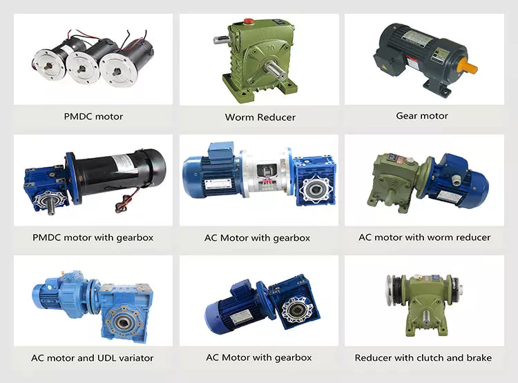
in Chiang Rai Thailand sales price shop near me near me shop factory supplier Udl Series Planetary Cone & Disk Step-Less Transmission Worm Gearbox Speed Variator with Motor manufacturer best Cost Custom Cheap wholesaler

  in Chiang Rai Thailand  sales   price   shop   near me   near me shop   factory   supplier Udl Series Planetary Cone & Disk Step-Less Transmission Worm Gearbox Speed Variator with Motor manufacturer   best   Cost   Custom   Cheap   wholesaler

Getting amassed cherished encounter in cooperating with foreign buyers, Entire use has been produced of all varieties of sophisticated methods and engineering to achieve excelsior manufacturing. our products are promoting effectively in the American, European, South American and Asian markets. We started out our organization from 1995 and now we are the 1 of the leaEPTmanufacturer of EPT EPT items. It focuses mostly on Keyless Locking Gadgets, Timing Belt EPTs, Roller Chains, EPT, Jaw Couplings, Gears and other areas.

These goods are developed in conformity with the Worldwide StXiHu (West Lake) Dis.Hu (West Lake) Dis.rd and the stXiHu (West Lake) Dis.Hu (West Lake) Dis.rds adopted in EPTized international locations (DIN EPT BS JIS) with up to information products, EPT EPT and ideal administration technique for top quality control. It features a team with wealthy encounter in this business, concentrating on EPT market place. So the products are of great top quality with competitive charges.

Our goal : Providing initial-course products and service to our buyers and company companions.

  in Chiang Rai Thailand  sales   price   shop   near me   near me shop   factory   supplier Udl Series Planetary Cone & Disk Step-Less Transmission Worm Gearbox Speed Variator with Motor manufacturer   best   Cost   Custom   Cheap   wholesaler

  in Chiang Rai Thailand  sales   price   shop   near me   near me shop   factory   supplier Udl Series Planetary Cone & Disk Step-Less Transmission Worm Gearbox Speed Variator with Motor manufacturer   best   Cost   Custom   Cheap   wholesaler